Form No. 3421-193 Rev B PT-36 Power Trowel Model No. Model No. Model No. Model No. Register at www.Toro.com. Original Instructions (EN) 68048—Serial No. 68049—Serial No. 68050—Serial No. 68051—Serial No.
Introduction WARNING This machine is used to create a smooth finish to concrete slabs. CALIFORNIA Proposition 65 Warning This product contains a chemical or chemicals known to the State of California to cause cancer, birth defects, or reproductive harm. The engine exhaust from this product contains chemicals known to the State of California to cause cancer, birth defects, or other reproductive harm.
Contents This manual identifies potential hazards and has safety messages identified by the safety alert symbol (Figure 2), which signals a hazard that may cause serious injury or death if you do not follow the recommended precautions. Safety ....................................................................... 4 Safe Operating Practices.................................... 4 Safety and Instructional Decals .......................... 6 Product Overview ....................................................
Safety – Extinguish all cigarettes, cigars, pipes, and other sources of ignition. Improper use or maintenance by the operator or owner can result in injury. To reduce the potential for injury, comply with these safety instructions and always pay attention to the safety alert symbol, which means Caution, Warning, or Danger—personal safety instruction. Failure to comply with the instruction may result in personal injury or death.
Maintenance and Storage • Let the engine cool before storing and do not store the machine near an open flame. • Position the machine on a level surface, set the throttle to slow, and shut off the engine. Wait for all movement to stop before adjusting, cleaning, or repairing. • Clean debris from drives, mufflers, and the engine to help prevent fires. Clean up oil or fuel spills. • Do not store fuel near flames or drain indoors. • Never allow untrained personnel to service the machine.
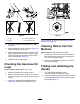
Safety and Instructional Decals Safety decals and instructions are easily visible to the operator and are located near any area of potential danger. Replace any decal that is damaged or missing. decal93-9084 93-9084 2. Tie-down point 1. Lift point decal125-4934 125–4934 1. Read the Operator’s Manual. 2. Disengage clutch 3. Engage clutch decal117-4979 117–4979 1.
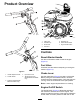
Product Overview g019519 g021560 Figure 4 1. Lifting point 5. Sediment cup 2. Fuel-tank cap 6. Recoil-starter handle 3. Choke lever 7. Engine On/Off switch 4. Fuel valve Controls Recoil-Starter Handle Pull the recoil-starter handle to start the engine (Figure 4). Fuel Valve Close the fuel valve when transporting or storing the machine (Figure 4). g020316 Figure 3 1. Handle-adjustment knob 4. Dyna-Clutch lever 2. Throttle handle 5.
engine. Rotate the On/Off switch to the Off position to shut off the engine. Throttle Handle Pull the throttle handle (Figure 3) to increase the engine speed, and push the handle to decrease the engine speed. Turn the handle clockwise to lock the throttle at a specific speed. Turn the handle counterclockwise to unlock the throttle. Handle-Adjustment Knob Turn the knob counterclockwise to loosen and move the handle to the desired position.
Specifications Operation Note: Specifications and design are subject to Note: Determine the left and right sides of the machine from the normal operating position. change without notice. Models 68048 and 68049 68050 and 68051 Width 92 cm (36.5 inches) 117 cm (46 inches) Length (operating) 177 cm (70 inches) 190.
g021590 g019746 Figure 10 Figure 9 1. Fill port 3. Oil-level upper limit 2. Dipstick 4. Oil-level lower limit 4. Unscrew the dipstick and wipe the end clean (Figure 9). 5. Slide the dipstick fully into the fill port (Figure 9) without threading it into the port. 6. Remove the dipstick and look at the end. If the engine oil level is low, slowly pour only enough oil into the fill port to raise the level to the Full mark on the dipstick (Figure 9). 7.
DANGER In certain conditions, fuel is extremely flammable and highly explosive. A fire or explosion from fuel can burn you and others and can damage property. • Fill the fuel tank outdoors, in an open area, when the engine is cold. Wipe up any fuel that spills. • Never fill the fuel tank inside an enclosed trailer. • Do not fill the fuel tank completely full. Add fuel to the fuel tank until the level is 6 to 13 mm (1/4 to 1/2 inch) below the bottom of the filler neck.
DANGER In certain conditions during fueling, static electricity can be released causing a spark which can ignite the fuel vapors. A fire or explosion from fuel can burn you and others and can damage property. • Always place fuel containers on the ground away from your vehicle before filling. • Do not fill fuel containers inside a vehicle or on a truck or trailer bed because interior carpets or plastic truck bed liners may insulate the container and slow the loss of any static charge.
Filling the Fuel Tank Models Fuel Tank Capacity 68048 and 68049 3.1 L (0.82 US gallons) 68050 and 68051 5.3 L (1.40 US gallons) Starting the Engine 1. Set the Dyna-Clutch lever to the STOP position, shut off the engine, wait for all moving parts to stop, and turn off the engine switch. 2. Allow the engine to cool. 3. Clean around the fuel-tank cap and remove it (Figure 12). 1. Set the throttle to full speed and set the Dyna-Clutch lever to the STOP position. 2.
Maintenance Recommended Maintenance Schedule(s) Maintenance Service Interval Maintenance Procedure After the first 25 hours • Change the engine oil. Before each use or daily • • • • • • Check the engine-oil level. Check the gearcase oil level. Clean debris from the air cleaner and engine. Lubricate the blade arms. Inspect the air cleaner elements. Check for loose fasteners. Every 40 hours • Check the belt, pulley alignment, belt tension, and belt-guide gap.
Engine Maintenance Lubrication Lubricating the Blade Arms Servicing the Air Cleaner Service Interval: Before each use or daily—Inspect the air cleaner elements. Service Interval: Before each use or daily Grease Type: General-purpose grease. 1. Clean around each grease fitting with a rag and lift the plastic cap off each grease fitting. 2. Pump several shots of grease into each fitting until it starts to ooze out of the bearing (Figure 14 and Figure 15). Every 50 hours—Clean the air filter elements.
4. Remove the cover (Figure 16 Box B). Note: Be careful to prevent dirt and debris from falling into the base. g019679 5. Remove the foam and paper elements from the base (Figure 16 Box C). 6. Remove the foam element from the paper element (Figure 16 Box D). 7. Inspect the foam and paper elements, and replace them if they are damaged or excessively dirty. Note: Never try to brush dirt off the paper element; brushing forces the dirt into the fibers. 8.
7. Remove the dipstick (Figure 9) and slowly pour oil into the fill hole until the oil is between the upper and lower fill marks on the dipstick. 8. Install and secure the dipstick. 9. Wipe up any spilled oil. Servicing the Gearcase Oil Service Interval: Every 150 hours g013375 Figure 17 Oil Type: 80W-90 gear oil that meets or exceeds API service category GL-5. Capacity: 1.18 L (1.
9. Apply thread-sealing compound to the threads of the plug. Servicing the Spark Plug 10. Install and tighten the plug until it is secure, and return the machine to an upright, level position. Service Interval: Every 100 hours—Inspect and adjust the spark plug; replace it if necessary. Note: The oil level in the sight glass of the plug Every 200 hours—Replace the spark plug. should be 3/4 full (Figure 20). Use an NGK BPR6ES spark plug or equivalent. 1.
Belt Maintenance Removing the Belt Guard 1. Checking the Belt, Pulley Alignment, Belt Tension, and Belt-Guide Gap Remove the 2 hex-washer head bolts (5/16 x 1 inch) that secure the belt guard to the belt-guard bracket (Figure 22). Service Interval: Every 40 hours 1. Remove the belt guard; refer to Removing the Belt Guard (page 19). 2. Move the Dyna-Clutch lever to the STOP position. 3. Check the condition of the belt for wear or damage.
Aligning the Pulleys Removing the Belt 1. Position the machine on a level surface, place the Dyna-Clutch lever in the STOP position, shut off the engine, and disconnect the spark-plug wire. 2. Remove the belt guard; refer to Removing the Belt Guard (page 19). 3. Slip the belt off the belt-tension pulley (Figure 23). 1. Place a straight-edge ruler across the engine pulley and the gearbox pulley (Figure 24). g024874 Figure 24 1. Straight edge 3. Engine pulley 2. Gearbox pulley 4. Setscrew 2.
Note: If the blades continue to rotate when the Dyna-Clutch is in the STOP position, there is too much tension on the clutch cable. Shut off the engine and repeat step 7 until the blades do not rotate when the engine is running and the Dyna-Clutch is in the STOP position. Adjusting the Belt Guide 1. Place the Dyna-Clutch lever in the RUN position. 2. Measure the air gap between the belt and the belt guide (Figure 26). g024904 Figure 25 1. Clutch bracket 4. Spring 2. Barrel 3. Cable housing 5.
Adjusting the ProPitch Linkage Rod Controls System Maintenance 1. Set the Dyna-Clutch lever to the Stop position, shut off the engine, and wait for all moving parts to stop. 2. Disconnect the wire from the spark plug. 3. Attach an overhead lift to the lifting point on the machine and lift if off of the ground. 4. Loosen the nut on the upper end of the linkage rod to allow slack in the lift cable (Figure 28). Adjusting the Tilt Knob 1.
Testing the Dyna-Clutch Lever Testing the Dyna-Clutch Operation Ensure that the area is clear of any debris or bystanders before beginning the testing procedures. 1. Start the trowel, engage the Dyna-Clutch lever, and run the machine for a few moments. 2. Move the Dyna-Clutch lever to the Stop position. 3. Watch the blades for any sign of continued rotation. g025040 Figure 29 If the blades do not stop, there is too much tension on the cable and spring.
g019517 Figure 32 1. Ruler 2. Spot on floor from first measurement 7. 3. Second blade Compare the 2 measurements. If the height of the second blade is not within 0.8 mm (1/32 inch) of the height of the first blade, adjust the second blade. 8. Loosen the locknuts on the blade (Figure 33). g019516 Figure 30 1. Stationary blade guard 2. Block 3. Measure from the floor to the leading edge of the blade. Note the measurement. 4.
Adjusting the Blade Arms Storage Adjust the blade arms if the machine still shakes excessively after the blades have been adjusted. 1. Place the machine on a flat surface. 2. Disconnect the spark plug. 3. Turn the tilt adjustment knob counter clockwise until all of the tension is off of the tilt adjustment cable and the blades are flat against the floor. Set the Dyna-Clutch lever to the Stop position, shut off the engine, and disconnect the spark-plug wire. 2.
Troubleshooting Problem Possible Cause Corrective Action The trowel blade turns when the recoil is pulled. 1. The clutch is engaged. 1. Disengage the Clutch. 2. The clutch is not properly adjusted. 3. The belt guide bracket is bent. 2. See Adjusting the Dyna-Clutch Lever. 3. See an Authorized Service Dealer. The trowel blades are wearing unevenly. 1. The blade arm is bent. 1. See Adjusting the Blade Arms. 2. The blade arm need to be adjusted. 3. The tilt mechanism needs to be adjusted. 4.
Notes:
California Proposition 65 Warning Information What is this warning? You may see a product for sale that has a warning label like the following: WARNING: Cancer and Reproductive Harm—www.p65Warnings.ca.gov. What is Prop 65? Prop 65 applies to any company operating in California, selling products in California, or manufacturing products that may be sold in or brought into California.