
Operator's Manual
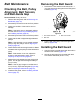
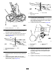

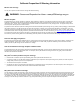

g019516
Figure30
1.Stationarybladeguard
2.Block
3.Measurefromtheoortotheleadingedgeof
theblade.Notethemeasurement.
4.Placeamarkonthebladeandonthespoton
theoorfromwherethemeasurementwas
taken(Figure31).
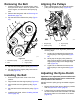
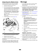
g019517
Figure31
1.Spotontheoorwherethe
measurementwastaken
3.Blade
2.Ruler
5.Rotatethebladesuntilthenextbladeisin
thesamepositionasthepreviouslymeasured
blade.
6.Measurethesecondbladefromthespot
previouslymarkedontheoortothesecond
bladesleadingedge(Figure32).
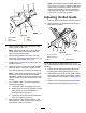
g019517
Figure32
1.Ruler
3.Secondblade
2.Spotonoorfromrst
measurement
7.Comparethe2measurements.
Iftheheightofthesecondbladeisnotwithin0.8
mm(1/32inch)oftheheightoftherstblade,
adjustthesecondblade.
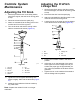
8.Loosenthelocknutsontheblade(Figure33).
g019518
Figure33
1.Rodendbearing4.Bladearmlever
2.Thrustplate5.Bladearm
3.Locknuts
9.Adjustthebladearmleverupordownas
necessarytomakethesecondbladeheight
thesameheightoftherstbladethatwas
measured.
10.Tightenthelocknuts.
11.Repeatasnecessaryfortheremainingblades.
24