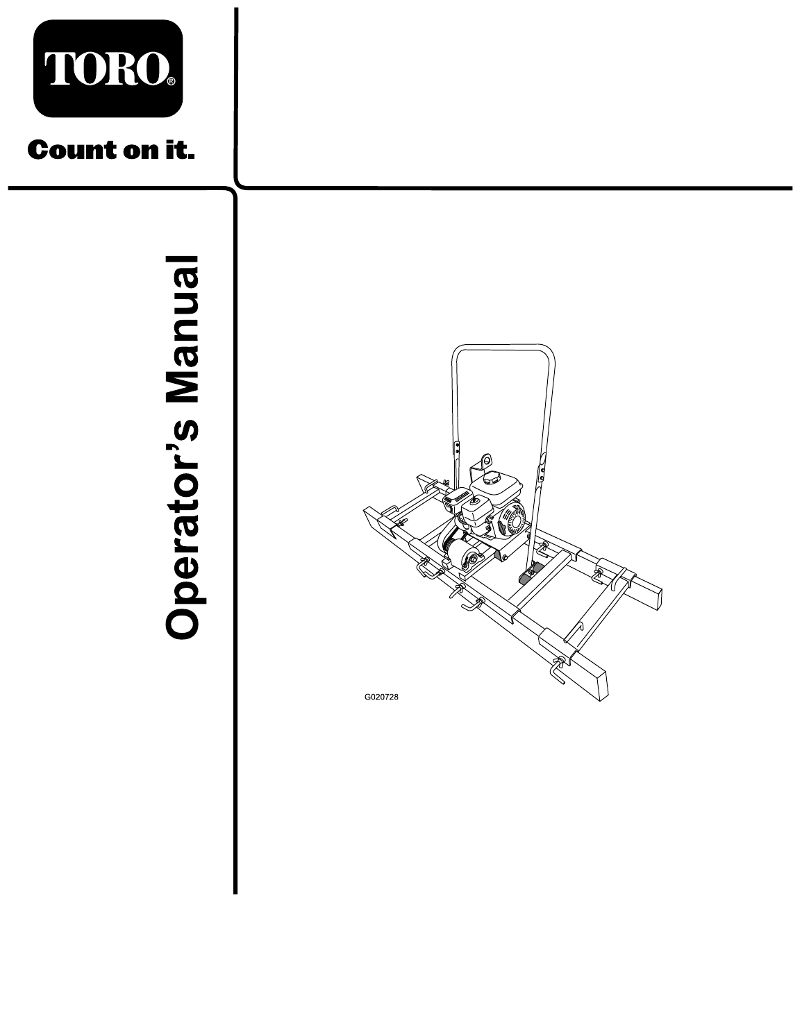
Form No. 3382-989 Rev A VS-400 and VS-800 Screed Model No. 68052—Serial No. 314000001 and Up Model No. 68053—Serial No. 314000001 and Up G020728 Register at www.Toro.com.
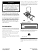
Whenever you need service, genuine Toro parts, or additional information, contact an Authorized Service Dealer or Toro Customer Service and have the model and serial numbers of your product ready. Figure 1 identifies the location of the model and serial numbers on the product. Write the numbers in the space provided. WARNING CALIFORNIA Proposition 65 Warning This product contains a chemical or chemicals known to the State of California to cause cancer, birth defects, or reproductive harm.
Contents Safety Safety ........................................................................... 3 Safe Operating Practices........................................... 3 Safety and Instructional Decals ................................. 5 Setup ............................................................................ 6 1 Installing the Handlebar......................................... 6 2 Installing the Tow Rope ......................................... 6 3 Installing the L-bolts .....................
Operation Maintenance and Storage • Never run an engine in an enclosed area. • Stop the engine and wait for all movement to stop before adjusting, cleaning, or repairing the machine. • Only operate the machine in good light. • Clean debris from the muffler and engine to help prevent • Only start the engine from the operator's position. fires. Clean up oil or fuel spillage. • Never operate with the guards not securely in place.
Safety and Instructional Decals Safety decals and instructions are easily visible to the operator and are located near any area of potential danger. Replace any decal that is damaged or lost. 125–8203 5. Warning—keep bystanders away. 1. Read the Operator’s Manual for information on starting the engine—1) Turn on the engine switch; 2) Close the choke and turn on the fuel switch; 3) Pull the recoil starter; 4) Open the choke. 2.
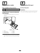
Setup 2 1 Installing the Tow Rope Installing the Handlebar Parts needed for this procedure: Parts needed for this procedure: 1 Left spreader 1 Right spreader 1 Upper handlebar 2 Pull grip 4 Bolt (5/16 x 1 inch) 2 Rope 4 Nut (5/16 inch) Procedure Procedure 1. Thread the end of the rope through a pull grip (Figure 4). Place the upper handlebar so that it can be installed using the nuts and bolts. (Figure 3).
3 4 Installing the L-bolts Checking the Oil Level Parts needed for this procedure: No Parts Required 10 L-bolt 10 Wingnut Procedure Before starting the engine for the first time, check the engine oil level; refer to Checking the Engine Oil Level (page 12). Assembling the L-bolts to the Machine and Spreaders 1. If not installed, thread the wingnuts onto the L-bolt (Figure 5). 6 5 4 1 1 2 3 G020862 Figure 5 1. L-bolt 4. Wingnut 2. Channel (frame) 5. Weldnut 3. Channel (spreader) 6.
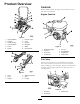
Product Overview Controls Become familiar with all the engine controls before you start and operate the machine. 1 12 Engine Controls 2 4 5 3 4 11 10 4 9 3 5 8 6 7 2 6 G020816 Figure 6 1 1. Upper handlebar 7. Eccentric guard 2. Fuel tank 3. Air-filter housing 8. L-bolt 9. Wingnut 4. Lower handlebar 10. Belt guard 5. Frame 6. Isolator 11. Muffler 12. Lifting bracket 7 8 G019744 Figure 8 6 5 1. Recoil-start handle 5. Fuel cap 2. Fuel valve 6. Oil cap/dipstick 3.
Choke Lever Engine On/Off Switch The choke lever (Figure 9) is required when starting a cold engine. Before pulling on the recoil-start handle, move the choke lever to the closed position. Once the engine is running, move the choke lever to the open position. Do not use the choke if the engine is already warmed up or the air temperature is high. The On/Off switch (Figure 10) allows the operator of the machine to start and stop the engine. This switch is located on the front of the engine.
Operation Note: Determine the left and right sides of the machine from the normal operating position. and/or engine damage which may not be covered under warranty. Important: Before operating the machine, check the fuel and oil levels, and remove debris from the machine. • Do not use gasoline containing methanol. • Do not store fuel either in the fuel tank or fuel containers over the winter unless a fuel stabilizer is used. Preparing to Use the Machine • Do not add oil to gasoline.
Add the correct amount of fuel stabilizer/conditioner to the fuel, and follow the directions of the manufacturer of the stabilizer. DANGER In certain conditions during fueling, static electricity can be released causing a spark which can ignite the gasoline vapors. A fire or explosion from gasoline can burn you and others and can damage property. Note: Fuel stabilizer/conditioner is most effective when mixed with fresh gasoline.
1 30 5W - 30 / 10W - 30 0 20 40 -20 -10 0 60 10 80 20 30 100 F o 40 C o g013375 Figure 14 Note: Toro Premium Engine Oil is available from your Authorized Toro Dealer. 1. Place the machine on a flat, level surface, and stop the engine. 2. Allow the engine to cool. 3. Clean around the oil dipstick. 4. Remove the oil cap/dipstick and wipe the end clean (Figure 15). 1 G020679 2 Figure 13 3 1. Maximum fuel level 4. Install the fuel cap securely (Figure 12). 5.
Starting and Stopping the Engine Starting the Engine 1. On the engine, move the throttle lever away from the Min position, 1/3 of the way toward the Max position (Figure 16); refer to Throttle Lever (page 9). G019747 Figure 17 Note: If the choke lever is set to the Closed position to start the engine, gradually move the choke lever back toward the Open position as the engine warms up. If the engine stalls or hesitates, move the choke lever back toward the Closed position until the engine runs smooth.
Installing and Removing the Screed Boards 5. Raise the rear of the machine 10 to 12 inches, and align the rear screed board to the rear U-channel of the frame (Figure 18). Note: Use straight 5 cm x 15 to 20 cm (2 inch x 6 to 8 inch) boards or 2-inch thick contoured material. 6. Align the screed board to the U-channel, and center the board to the machine (Figure 18). Maximum screed board widths: 7. Secure the screed board to the machine by tightening all the L-bolts and wing nuts (Figure 18).
Screeding a Concrete Surface 2. Start the engine; refer to Starting the Engine (page 13). Leveling the Concrete Surface 3. Move the throttle lever to the Fast position; refer to Throttle Lever (page 9). 4. Pull the screed in slow, steady motion along the concrete forms (Figure 20). This procedure levels a freshly poured concrete project to the form height. Note: Ensure that an adequate amount of concrete is loaded ahead of the forward screed board for the entire screeding pass.
Lifting the Machine Moving the Machine with the Lifting Plate Important: Use lifting equipment with a 61 kg (134 lb) or greater lift capacity. 1. Remove the spreaders and screed boards from the machine; refer to Removing the Spreaders and Screed Boards (page 14). 2. Move the lever for the fuel valve to the Off position, refer to Fuel Valve (page 8). 3. Align the hook, strap, or cable of the lifting equipment to the hole in the lifting bracket (Figure 21). 1 2 G020991 Figure 21 1. Lifting equipment 2.
Maintenance Note: Determine the left and right sides of the machine from the normal operating position. Recommended Maintenance Schedule(s) Maintenance Service Interval Maintenance Procedure After the first 25 hours • Inspect and adjust the belt. After the first 50 hours • Change the oil. Before each use or daily • • • • Check the engine oil level. Grease the machine. Inspect the air cleaner elements. Check for loose fasteners. After each use • Clean the machine.
CAUTION Disconnect the wires from the spark plugs before you do any maintenance. Set the wires aside so that they do not accidentally contact the spark plugs. Premaintenance Procedures Lubrication Preparing the Machine for Maintenance Service Interval: Before each use or daily Greasing the Machine Grease eccentric bearings every 8 operating hours and immediately after every washing. 1. Move the machine to a level surface. Grease Type: Lithium-based grease. 2.
Engine Maintenance Note: Be careful to prevent dirt and debris from falling into the base. Servicing the Air Cleaner 5. Remove the foam and paper elements from the base (Figure 24). Service Interval: Before each use or daily—Inspect the air cleaner elements. Every 50 hours—Clean the air filter elements. Clean them more frequently in dusty operating conditions. Every 300 hours/Yearly (whichever comes first)—Replace the paper air cleaner element. Replace it more frequently in dusty operating conditions.
Changing the Engine Oil Note: Dispose of the used oil at a certified recycling center. Service Interval: After the first 50 hours/Monthly (whichever comes first)—Change the oil. Filling the Engine Crankcase with Oil Every 100 hours/Every 6 months (whichever comes first)—Change the oil. Important: Use 4-stroke motor oil that meets or exceeds the requirements for API service category SJ or later (or equivalent).
1 2 3 4 Figure 28 1. Spark plug 2. Wire 4. Clean around the spark plug. 5. Rotate the spark plug counterclockwise using a 20 mm (13/16 inch) spark-plug wrench to remove the plug and sealing washer (Figure 29). G019746 Figure 27 1. Fill port 3. Oil level (upper limit) 2. Oil cap/dipstick 4. Oil level (lower limit) 2. Slowly pour approximately 80% of the specified amount of oil into the fill port (Figure 27). 3.
1 2 3 Fuel System Maintenance 4 Servicing the Fuel System Cleaning the Sediment Cup Service Interval: Every 100 hours/Every 6 months (whichever comes first)—Clean the sediment cup. Yearly or before storage—Clean the fuel sediment cup. G019300 Figure 30 1. Side electrode 2. Center electrode 3. Insulator 4. 0.7 to 0.8 mm (0.028 to 0.031 inch) gap Underneath the fuel valve is a sediment cup to catch dirt in the fuel. 1.
Drive System Maintenance 10. Move the lever of the fuel valve to the On position (all the way to the right) and check for leaks. If it leaks, replace the O-ring. Lubricating the Clutch Service Interval: Monthly 1. From the back of the machine, locate the clutch cover that is between the lifting bracket and the belt (Figure 32). 7 1 6 5 4 2 3 3 G020904 Figure 32 1. Lifting bracket 5. Belt 2. Belt guard 6. Fixed cone 3. Clutch cover 4. Sliding cone 7. SAE 5W-30 oil 2.
Belt Maintenance 1 2 3 Removing and Installing the Belt Guard Removing the Belt Guard 1. At the back of the machine, locate the right-cross channel of the frame (Figure 33 and Figure 34). 5 6 4 Note: The back of the machine is on the side opposite from the eccentric guard. G020916 Figure 34 1. Engine deck 4. Shoulder bolt (3/8 inch) 2. Right-cross channel 5. Belt guard 3. Spacer 6. Bolt (1/4 inch) Note: The spacer will support the engine when the 2 bolts (3/8 inch) are removed. 3.
Installing the Belt Guard 1 1. Align the belt guard over the pulleys. 2. Apply medium strength (service removable thread locking compound to the threads of the bolt (1/4 inch and 2 shoulder bolts (3/8 inch). 3. Align the (1/4 inch) hole in the belt guard with the hole in the belt guard bracket (Figure 34 and Figure 36). 4. Thread the bolt (1/4 inch) through the belt guard and into the belt-guard bracket (Figure 34 and Figure 36). Note: Do not tighten the 1/4 inch bolt. 5.
Installing the Belt 1. Align the belt over the clutch (Figure 37). 2. Pull the belt toward the eccentric pulley (Figure 36). 3. Slip the belt over the shoulder of the eccentric pulley (Figure 36). Note: Rotate the eccentric pulley by hand to help install the belt. 1 2 3 3 1 2 1 1 4 Adjusting the Belt G020966 1. At the clutch, align the belt against the fixed cone. Figure 39 Note: Use a flat bladed screwdriver to position the belt against the fixed cone. 4 1 2 3 1. Bolt 3. Engine deck 2.
Cleaning Storage Cleaning the Machine Important: You can wash the machine with mild detergent and water. Do not pressure wash the engine or eccentric bearings. Regular cleaning and washing will increase the life span of the machine. Clean the machine after each use, before the cement dries. 1. Remove concrete, sand, and aggregate from the external parts of the machine, especially the engine. Clean dirt from the outside of the engine's cylinder head fins and housing.
11. Store the machine unit in a clean, dry garage or storage area. 12. Cover the machine to protect it and keep it clean.
Troubleshooting Problem The engine will not start. Possible Cause 1. The fuel-valve lever is in the Off position. 1. Move the fuel-valve lever to the On position. 2. The choke is closed. 2. Open the choke when starting a hot engine. 3. Close the choke when starting a cold engine. 4. Rotate the switch to the On position. 3. The choke is open. 4. The engine On/Off switch is in the Off position. 5. The engine oil level is low (engines with the oil-level switch). 6. The fuel tank is empty. 7.
Notes: 30
Notes: 31
The Toro Warranty A limited warranty (see warranty periods below) Conditions and Products Covered The Toro Company and its affiliate, Toro Warranty Company, pursuant to an agreement between them, jointly warrant your Toro Concrete, Masonry, and Compaction Equipment Products listed below to be free from defects in materials or workmanship. This warranty covers the cost of parts and labor, but you must pay transportation costs. for that part.