
Operator's Manual
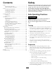
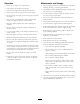

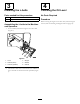
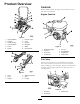
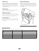
Table Of Contents

ProductOverview
1
2
4
4
5
6
7
8
9
10
11
12
3
G020816
Figure6
1.Upperhandlebar7.Eccentricguard
2.Fueltank8.L-bolt
3.Air-lterhousing
9.Wingnut
4.Lowerhandlebar10.Beltguard
5.Frame
11.Mufer
6.Isolator
12.Liftingbracket
6
5
4
4
3
2
1
G020817
Figure7
1.Cleat4.Channel(spreader)
2.L-bolt5.Rope
3.Wingnut6.Pullgrip
Controls
Becomefamiliarwithalltheenginecontrolsbeforeyoustart
andoperatethemachine.
EngineControls
1
2
3
4
5
6
7
8
G019744
Figure8
1.Recoil-starthandle5.Fuelcap
2.Fuelvalve
6.Oilcap/dipstick
3.Chokelever7.Oil-drainplug
4.Throttlelever
8.On/Offswitch
FuelValve
Thefuelvalve(Figure9)islocatedunderneaththechoke
lever.MovetheleverforthefuelvalvetotheOnposition
beforeattemptingtostarttheengine.Whenyouhavenished
screeding,stoptheengineandmovethefuelvalveleverto
theOffposition.
G020998
1 2
3
Figure9
1.Fuelvalve3.Throttlelever
2.Chokelever
8