Form No. 3377-563 Rev B VS-70 and VS-80 Screed Model No. 68054—Serial No. 313000001 and Up Model No. 68055—Serial No. 313000001 and Up g021465 Register at www.Toro.com.
Whenever you need service, genuine Toro parts, or additional information, contact an Authorized Service Dealer or Toro Customer Service and have the model and serial numbers of your product ready. Figure 1 identifies the location of the model and serial numbers on the product. Write the numbers in the space provided. WARNING CALIFORNIA Proposition 65 Warning This product contains a chemical or chemicals known to the State of California to cause cancer, birth defects, or reproductive harm.
Contents Safety Introduction .................................................................. 2 Safety ........................................................................... 3 Safe Operating Practices........................................... 3 Safety and Instructional Decals ................................. 5 Setup ............................................................................ 6 1 Installing the Handlebar and Throttle Cable ..........................................................
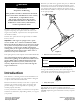
Operation Maintenance and Storage • Never run an engine in an enclosed area. • Stop the engine and wait for all movement to stop before adjusting, cleaning, or repairing the machine. • Only operate the machine in good light. • Clean debris from the muffler, spark arrester, and engine • Only start the engine from the operator's position. to help prevent fires. • Never operate with the covers not securely in place.
Safety and Instructional Decals Safety decals and instructions are easily visible to the operator and are located near any area of potential danger. Replace any decal that is damaged or lost. 117–2718 125–8192 1. Read the Operator’s Manual for 4. Warning—keep away from moving information on starting the engine—1) parts; keep all guards and shields in Turn the engine switch on; 2) Close the place. choke; 3) Pull the recoil start handle; 4) Open the choke. 2.
Setup 1 Installing the Handlebar and Throttle Cable 4 5 6 3 No Parts Required 2 1 Procedure g022042 1. Slide the handlebar into position (Figure 3). 2 Figure 4 1. Cable fitting 4. Cable 2. Washer 3. Nut 5. Cable anchor 6. Cable stop 5. Move the assembly into place, let the cable stop slide into place, and tighten the cable fitting and nut; refer to Figure 5. 4 3 1 1 2 3 4 5 6 g022043 Figure 5 1. Cable fitting 4. Cable 2. Washer 3. Nut 5. Cable anchor 6.
Product Overview Controls 1 2 Become familiar with all the engine controls before you start and operate the machine. Engine Controls 3 2 3 1 4 5 6 g021466 Figure 6 1. Throttle lever 2. handle bar 4. Lift handle 5. Board clamp 3. Engine 6. Aluminum board 6 5 4 g021468 Figure 7 7 1. Air cleaner cover 4. Fuel cap 2. Priming bulb 5. Choke lever 3. Recoil starter 6.
Choke Lever 1 The choke lever (Figure 10) is required when starting a cold engine. Before pulling on the recoil-start handle, move the choke lever to the closed position. Once the engine is running, move the choke lever to the open position. Do not use the choke if the engine is already warmed up or the air temperature is high. g021469 2 Figure 8 1. Spark arrestor 2. Oil cap Priming bulb 1 The priming bulb (Figure 9) is located above the fuel cap. g021480 Figure 10 1.
Recoil-start Handle To start the engine, pull the recoil-start handle (Figure 7). Engine On/Off Switch ON OF The On/Off switch (Figure 12) allows the operator of the machine to start and stop the engine. This switch is located on the front of the engine. It is marked l (On) and O (Off). Rotate the On/Off switch to the On position to start and run the engine. Rotate the On/Off switch to the Off position to stop the engine.
Operation Important: Before operating the machine, check the fuel and oil levels, and remove debris from the machine. • Use the resting position when leaving the machine. (Figure 14). Never leave the engine running while the machine is in the rest position. Always set the machine on a flat surface. Preparing to Use the Machine • Review all of the safety decals on the machine. • Use a hard hat, hearing protection, tight-fitting gloves • • • • without drawstrings or loose cuffs, and eye protection.
• Use the gas-filling position whenever you fill the gas DANGER tank (Figure 15). With a firm hand on the shaft of the machine and a gas can next to the operator, unscrew the gas cap, pickup the gas can, and fill up the gas tank on the machine. In certain conditions, gasoline is extremely flammable and highly explosive. A fire or explosion from gasoline can burn you and others and can damage property. • Fill the fuel tank outdoors, in an open area, when the engine is cold.
Filling the Fuel Tank WARNING Fuel tank capacity: 0.65L (0.172 US gallon) Gasoline is harmful or fatal if swallowed. Long-term exposure to vapors can cause serious injury and illness. Important: The unused space in the tank allows the gasoline to expand with changes in temperature. Do not fill the fuel tank completely full. • Avoid prolonged breathing of vapors. 1. Stop the engine; refer to Stopping the Engine (page 14), move the machine to a level surface, and allow the engine to cool.
1. Move the machine on a flat, level surface, and stop the engine. 2. Allow the engine to cool. 3. Clean around the oil dipstick. 4. Remove the oil cap/dipstick and wipe the end clean (Figure 19). 1 g021474 Figure 17 2 6. Install the fuel cap securely (Figure 16). 7. Wipe up any spilled gasoline. Checking the Engine Oil Level Service Interval: Before each use or daily Important: Use 4-cycle motor oil that meets or exceeds the requirements for API service category SJ or later (or equivalent).
Screeding a Concrete Surface 5. Pull the recoil-start handle lightly until you feel resistance, then pull the handle briskly (Figure 20). Note: Return the recoil-start handle gently. Installing the Aluminum Screed Board Note: Only use equilateral triangle aluminum screed boards designed for this machine. Screed board widths: VS-70 VS-80 1.2 meters (4 feet) x x 1.8 meters (6 feet) x x 2.4 meters (8 feet) x x 3.0 meters (10 feet) x x 3.7 meters (12 feet) x 4.3 meters (14 feet) x 4.
Note: To remove the screed board, reverse the steps of this procedure. 7. At the end of the screed pass, move the engine throttle to the idle position and allow the engine to idle for 1 minute. Leveling the Concrete Surface 8. Stop the engine and move the screed off the cement; refer to Stopping the Engine (page 14). This machine can float over wet concrete with or without the aid of forms. 1.
Maintenance Note: Determine the left and right sides of the machine from the normal operating position. Recommended Maintenance Schedule(s) Maintenance Service Interval Maintenance Procedure After the first 50 hours • Change the oil. Before each use or daily • Check the engine oil level. • Inspect the air cleaner elements. • Check for loose fasteners. After each use • Clean the machine. Every 25 hours • Change the oil when operated under heavy loads or in high temperatures.
CAUTION Disconnect the wire from the spark plug before you do any maintenance. Set the wire aside so that it does not accidentally contact the spark plug. Premaintenance Procedures 2. Pull the spark-plug wire off the terminal of the spark plug (Figure 24). 1 2 Preparing the Machine for Maintenance 1. Turn the machine off, move it to a level surface, and set it down in the rest position. 2. Ensure that the engine and muffler are cool. 3. Remove the top cover and the spark-plug wire. 4.
Engine Maintenance 9. Wipe dirt from the base and the cover with a moist rag. Note: Be careful to prevent dirt and debris from entering the air duct leading to the carburetor. Servicing the Air Cleaner 10. Install the foam elements and ensure that it is properly positioned. Service Interval: Before each use or daily—Inspect the air cleaner elements. 11. Securely install the air cleaner cover. Every 50 hours—Clean the air filter elements. Clean them more frequently in dusty operating conditions. 12.
Changing the Engine Oil Filling the Engine Crankcase with Oil Service Interval: After the first 50 hours/Monthly (whichever comes first)—Change the oil. Important: Use 4-stroke motor oil that meets or exceeds the requirements for API service category SJ or later (or equivalent). Always check the API service label on the oil container to be sure it includes the SJ or later (or equivalent). Running the engine with a low oil level can cause engine damage. This type of damage is not covered by warranty.
Checking the Spark Plug 2. Slowly pour approximately 80% of the specified amount of oil into the fill port (Figure 28). 3. Add additional oil to bring the oil level to the proper fill amount; refer to (Figure 28). 4. Install the oil cap/dipstick (Figure 28). Note: Use a gapping tool/feeler gauge to check and adjust the air gap. Install a new spark plug if necessary. Air Gap: 0.6 to 0.7 mm (0.024 to 0.028 inch) Spark plug type: CM5H (NKG), CMR5H (NGK), or equivalent 1.
• When installing an in-service spark plug, tighten the plug an additional 1/8 to 1/4 turn. • When installing a new spark plug, tighten the plug an additional 1/2 turn. 4. Install the spark-plug wire pushing the wire onto the terminal of the plug (Figure 29). Cleaning the Spark Arrester 1. Remove the top cover and spark plug wire. 1 2. Remove the spark arrester (Figure 31). 1 2 g021487 Figure 32 1. Spark arrestor g021479 Figure 31 1. Screw 2. Spark arrestor 3.
Fuel System Maintenance Servicing the Fuel System 1 2 Cleaning the fuel filter Service Interval: Every 100 hours/Yearly (whichever comes first)—Clean the fuel filter. Inside the fuel tank is a fuel filter to catch dirt in the fuel. 1. Turn off the engine; refer to Stopping the Engine (page 14) and place the machine in the resting position (Figure 14). 2. Ensure that the engine and the exhaust system surfaces are cool. 3. Disconnect the wire from the spark plug; refer to Removing the Spark Plug (page 20).
Cleaning Storage Cleaning the Machine Important: You can wash the machine with mild detergent and water. Do not pressure wash the engine. 1. Remove concrete, sand, and aggregate from the external parts of the machine, especially the engine. Clean dirt from the outside of the engine's cylinder head fins and housing. Regular cleaning and washing will increase the life span of the machine. Clean the machine after each use, before the cement dries.
Troubleshooting Problem The engine will not start. Possible Cause 1. The fuel-valve lever is in the Off position. 1. Move the fuel-valve lever to the On position. 2. The choke is closed. 2. Open the choke when starting a hot engine. 3. Close the choke when starting a cold engine. 4. Rotate the switch to the On position. 3. The choke is open. 4. The engine On/Off switch is in the Off position. 5. The fuel tank is empty. 6. The engine contains bad/old fuel. 7.
Notes: 25
Notes: 26
Notes: 27
Concrete, Masonry, and Compaction Equipment The Toro Warranty A limited warranty (see warranty periods below) Conditions and Products Covered The Toro Company and its affiliate, Toro Warranty Company, pursuant to an agreement between them, jointly warrant your Toro Concrete, Masonry, and Compaction Equipment Products listed below to be free from defects in materials or workmanship. This warranty covers the cost of parts and labor, but you must pay transportation costs.