Form No. 3448-245 Rev A MB TX 2500S Tracked Mud Buggy Model No. 68141—Serial No. 400000000 and Up Model No. 68141G—Serial No. 400000000 and Up Register at www.Toro.com.
Introduction It is a violation of California Public Resource Code Section 4442 or 4443 to use or operate the engine on any forest-covered, brush-covered, or grass-covered land unless the engine is equipped with a spark arrester, as defined in Section 4442, maintained in effective working order or the engine is constructed, equipped, and maintained for the prevention of fire. This machine is intended to be used by professional, hired operators in commercial applications.
Cleaning the Blower Housing............................ 25 Fuel System Maintenance ................................... 26 Replacing the Fuel Filter ................................... 26 Draining the Fuel Tank ...................................... 26 Removing the Fuel Tank ................................... 27 Electrical System Maintenance ........................... 27 Servicing the Battery......................................... 27 Servicing the Fuses ..........................................
Safety Improperly using or maintaining the machine can result in injury. To reduce the potential for injury, comply with these safety instructions and always pay attention to the safety-alert symbol (Figure 2), which means Caution, Warning, or Danger—personal safety instruction. Failure to comply with the instruction may result in personal injury or death. General Safety • Read and understand the contents of this Operator’s Manual before starting the engine.
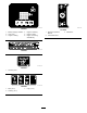
decal132-8961 decal137-0575 132-8961 137-0575 1. Battery charging condition 4. Hopper is lowering. 2. Hour meter 5. Hopper is down. 3. Hopper is raising. 6. Hopper is lowering automatically. 1. Read the Operator’s Manual. 2. Transmission fluid decal133-8062 133-8062 decal132-9051 132-9051 1. Tie-down point decal132-9052 132-9052 1. Main (15 A) 3. Logic (7.5 A) 2. Auxiliary (15 A) 5 3.
decal139-7202 139-7202 1. Parking—brake release 10. Warning—engage the parking brake, shut off the engine, and remove the key before leaving the operators position. 2. Parking brake 11. Move the handles in to operate. 3. Warning—read the Operator’s Manual; wear hearing protection. 12. Left traction controls 4. Warning—all operators should read the Operator’s Manual and be trained before operating the machine. 13. Raise hopper 5. Warning—stay away from moving parts; keep all guards and 14.
decal139-7223 139-7223 1. Read the Operator’s Manual.
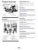
Parking Brake Lever Product Overview To engage the parking brake, pull back the lever. (Figure 4). To disengage the parking brake, push the lever forward. Hour Meter The hour meter records the number of hours the engine has operated. It operates when the engine is running. Use these times for scheduling regular maintenance (Figure 4). g322676 Figure 3 1. Hopper 4. Fuel-tank cap 2. Hood 5. Operator platform Choke Control Use the choke to start a cold engine. Pull the choke knob up to engage it.
Specifications Operation Note: Specifications and design are subject to Note: Determine the left and right sides of the machine from the normal operating position. change without notice. Width 90.2 cm (35-1/2 inches) Length 268.0 cm (105-1/2 inches) Height 130.18 cm (51.25 inches) Weight 855.5 kg (1,886 lb) Hopper capacity Maximum load Discharge Height 0.45 m3 (16 Before Operation Important: Before operating, check the fuel and oil level, and remove debris from the machine.
• Do not store the machine or fuel container where DANGER there is an open flame, spark, or pilot light, such as on a water heater or other appliance. In certain conditions, fuel is extremely flammable and highly explosive. A fire or explosion from fuel can burn you and others and can damage property. • If you spill fuel, do not attempt to start the engine; avoid creating any source of ignition until the fuel vapors have dissipated.
Using Stabilizer/Conditioner DANGER In certain conditions during fueling, static electricity can be released causing a spark, which can ignite the fuel vapors. A fire or explosion from fuel can burn you and others and can damage property. Use fuel stabilizer/conditioner in the machine to keep the fuel fresh longer when used as directed by the fuel-stabilizer manufacturer. Important: Do not use fuel additives containing methanol or ethanol.
During Operation • Check for overhead clearance (i.e., electrical During Operation Safety • Do not overload the hopper and always keep the wires, branches, and doorways) before driving under any objects and do not contact them. load level when operating the machine. General Safety Slope Safety • The owner/user can prevent and is responsible • Slopes are a major factor related to loss-of-control for accidents that may cause personal injury or property damage.
Operating the Throttle to lose traction. Loss of traction to the wheels or tracks may result in sliding and a loss of braking and steering. The machine can slide even if the wheels or tracks are stopped. The throttle control moves between FAST and SLOW positions (Figure 7). • Remove or mark obstacles such as ditches, holes, Always use the FAST position when moving the machine. ruts, bumps, rocks or other hidden hazards. Tall grass can hide obstacles. Uneven terrain could overturn the machine.
Starting the Engine 1. Engage the parking brake. 2. Engage the choke. Shutting Off the Engine Note: A warm or hot engine may not require choking. You may need to repeat the starting cycle when you start the engine for the first time after you have filled a completely empty fuel system with fuel. 1. Move the throttle between the FAST and SLOW positions. 2. Engage the parking brake. 3. Turn the key switch to the OFF position and remove the key.
Important: Do not use a hammer to remove material from the inside of the hopper; this may cause damage to the machine. 4. Clean any debris from under the hopper. 5. Wipe away debris from the air cleaner. 6. Clean any debris buildup on the engine and in the transmission with a brush or blower. Important: Blow out dirt rather than wash it out. If you use water, keep it away from electrical parts and hydraulic valves. Do not use a high-pressure washer.
5. Connect the hose fittings. 6. Use a hoist or have 2 people hold up the hopper and remove the cylinder lock. Moving a Non-Functional Machine 7. Carefully lower the hopper to the machine frame. Important: Do not tow or pull the machine without first opening the bypass valves in this procedure, or you will damage the hydraulic system. Raising the Hopper without Power 1. Raise the machine and support it using jack stands rated for the weight of the machine; refer to Specifications (page 9). 2.
Transporting the Machine Lifting the Machine Use a heavy-duty trailer or truck with full-width ramps to transport the machine. Ensure that the trailer or truck has all the necessary brakes, lighting, and marking as required by law. Please carefully read all the safety instructions. Knowing this information could help you, your family, pets or bystanders avoid injury. Refer to your local ordinances for trailer and tie-down requirements.
Maintenance Note: Determine the left and right sides of the machine from the normal operating position. Recommended Maintenance Schedule(s) Maintenance Service Interval Maintenance Procedure After the first 10 hours • Check and adjust the track tension (every 10 hours until 50 hours). Before each use or daily • • • • • • • • Check the engine-oil level. Clean the blower housing (more often under extremely dusty, dirty conditions). Check the condition of the track. Check the parking brake operation.
Pre-Maintenance Procedures • Use cardboard or paper to find hydraulic leaks. • Safely relieve all pressure in the hydraulic system before performing any work on the hydraulic system. Maintenance Safety Releasing the Cushion for Rear Access • Park the machine on a level surface, engage the parking brake, and shut off the engine. Wait for all movement to stop and allow the machine to cool before adjusting, servicing, cleaning, or storing the machine.
Using the Cylinder Lock 2. Fully raise the hopper. 3. Shut off the engine. 4. Park the machine on a level surface, move the motion-control levers to the NEUTRAL-LOCK position, engage the parking brake, and fully raise the hopper. Remove the cotterless pins securing the cylinder lock. 5. Place the cylinder lock on the posts inside the machine frame and secure with the cotterless pins. Remove the 2 cotterless pins securing the cylinder lock to the machine. 6. Lower the hopper.
Lubrication Engine Maintenance Greasing the Machine Servicing the Air Cleaner Service Interval: Every 50 hours Service Interval: Every 25 hours—Service or replace the air-cleaner foam element (more often under extremely dusty, dirty conditions). When operating the machine under normal conditions, lubricate all grease fittings for the bearings and bushings with No. 2 lithium grease. Lubricate the bearings and bushings immediately after every washing, regardless of the interval listed.
Checking the Engine-Oil Level Service Interval: Before each use or daily Important: Remember to add 80% of the oil, and then gradually fill it to the Full mark on the dipstick. Important: Do not run the engine with the oil level above the Full mark or below the low mark. Otherwise, you may damage the engine. g028106 Figure 24 1. Air-cleaner cover 3. Paper element 1.
Changing the Engine Oil and Filter Service Interval: Every 100 hours Oil Type:: Detergent oil (API service SJ or higher) Engine Oil Capacity: 1.9 L (64 fl oz) g185888 Viscosity: Refer to the table below. g031623 Figure 27 g017552 Figure 26 B. Change the engine oil while the engine is warm. 4. Note: Dispose of the used oil at a recycling center. 1.
g243623 Figure 29 g027477 Figure 28 5. Servicing the Spark Plugs Slowly pour approximately 80% of the specified oil into the filler tube (Figure 29). Service Interval: Every 100 hours—Check the spark plug. Every 300 hours—Replace the spark plug. The spark plugs are RFI compliant. Equivalent alternate brand plugs can also be used. Type: Champion XC12YC Air Gap: 0.76 mm (0.
Removing the Spark Plug Installing the Spark Plug 1. Park the machine on a level surface, move the motion-control levers to the NEUTRAL-LOCK position, engage the parking brake, and lower the hopper. 2. Shut off the engine and remove the key. Allow the engine to cool. 3. Before removing the spark plug(s), clean the area around the base of the plug to keep dirt and debris out of the engine. 4. Remove the spark plug (Figure 30).
Draining the Fuel Tank Fuel System Maintenance You can drain the fuel tank by removing it and pouring the fuel out of the fill neck; refer to Removing the Fuel Tank (page 27). You can also drain the fuel tank by using a siphon in the following procedure. Replacing the Fuel Filter Service Interval: Every 100 hours/Yearly (whichever comes first) (more often under dusty, dirty conditions). 1.
Removing the Fuel Tank 1. Lower the platform. 2. Release the cushion; refer to Releasing the Cushion for Rear Access (page 19). 3. Remove the cross bracket (Figure 35). Electrical System Maintenance Servicing the Battery Service Interval: Every 50 hours DANGER Battery electrolyte contains sulfuric acid, which is fatal if consumed and causes severe burns. Do not drink electrolyte and avoid contact with skin, eyes or clothing.
Charging the Battery WARNING Charging the battery produces gasses that can explode. Never smoke near the battery and keep sparks and flames away from battery. Important: Always keep the battery fully charged (1.265 specific gravity) to prevent battery damage when the temperature is below 0°C (32°F). 1. Remove the battery from the chassis; refer to Removing the Battery (page 27). 2. Perform the following steps to check the electrolyte level: A. Ensure that the cell covers are free from dirt and debris.
Servicing the Fuses Drive System Maintenance The electrical system is protected by fuses and requires no maintenance. If a fuse blows, check the component or circuit for a malfunction or short. Servicing the Tracks 1. Release the cushion from the rear of the machine. 2. Pull out the fuse to remove or replace it (Figure 38). 3. Install the cushion to the rear of the machine. Service Interval: Before each use or daily—Check the condition of the track.
Adjusting the Track Tension If you place the tab of the tensioning tool along the rear edge of the tension nut, the other end of the tensioning tool should align with the edge of the tension arm as shown in Figure 40. If the distance is not correct, adjust the track tension using the following procedure: Note: If the tensioning tool is not available, the 4. Raise the machine so that the tracks are off the ground. 5. Clean the drive sprocket, the front wheel, and the road wheels.
8. Inspect the condition of the wheels. If the wheels show signs of wear, replace them at this time. 9. Beginning at the drive sprocket, coil the new track around the sprocket, ensuring that the lugs on the track fit between the spacers on the sprocket (Figure 41). 10. Replacing the Drive Belt Service Interval: Every 300 hours 1. Push the track under the lugs and between the road wheels (Figure 41).
Controls System Maintenance Adjusting the Motion-Control Levers If the motion-control levers do not align horizontally, adjust the right side motion-control lever. 1. Park the machine on a level surface, lower the hopper, engage the parking brake, shut off the engine, and remove the key. 2. Push the motion-control levers down out of the NEUTRAL-LOCK position (Figure 46). 3. Check if the right motion-control lever aligns horizontally with the left motion-control lever (Figure 46). g189559 Figure 44 1.
4. Release the parking brake. 5. Move the motion-control levers forward. Note: The machine should move forward. Note: If the machine does not move forward, refer to Adjusting the Parking Brake (page 33). 6. Engage the parking brake and shut off the machine. Adjusting the Parking Brake g189389 Figure 47 1. Cam 7. 1. Remove the fuel tank; refer to Removing the Fuel Tank (page 27). 2. Inside the left side of the control tower, adjust the nuts until the cables are taught (Figure 48). 2.
Hydraulic System Maintenance WARNING Hydraulic fluid escaping under pressure can penetrate skin and cause injury. Fluid injected into the skin must be surgically removed within a few hours by a doctor familiar with this form of injury; otherwise gangrene may result. g203616 Figure 49 • Keep your body and hands away from pinhole leaks or nozzles that eject high-pressure hydraulic fluid. 2. Sight window • Use cardboard or paper to find hydraulic leaks; never use your hands. 5. 1. Expansion-tank cap 3.
2. Shut off the engine, and remove the key. Allow the engine to cool. 3. Lower the cushion and remove the fuel tank; refer to Removing the Fuel Tank (page 27). 4. Remove the 9 bolts (5 rear, 4 side) from the skid plate and remove the skid plate (Figure 51). 10. Loosen the vent plug in each transmission until loose (Figure 53). Note: This allows air to escape the hydraulic system as you add hydraulic fluid. g325648 g203517 Figure 51 1. Rear bolts (5) Figure 53 3. Side bolts (4) 1. Vent plug 2.
Bleeding the Hydraulic Drive System Servicing the Hydraulic Lift and Slew System Bleed the traction hydraulic system whenever you perform maintenance on the hydrostatic transmission or add hydraulic fluid to the expansion tank. 1. Hydraulic-Fluid Specifications Reservoir-tank capacity: 6.6 L (1.75 US gallons) Park the machine on a level surface, move the motion-control levers to the NEUTRAL-LOCK position, engage the parking brake, and lower the hopper. 2. Shut off the engine, and remove the key.
Changing the Hydraulic Fluid for the Lift and Slew System Service Interval: Every 300 hours 1. Park the machine on a level surface, move the motion-control levers to the NEUTRAL-LOCK position, engage the parking brake, raise the hopper, and install the cylinder lock. 2. Shut off the machine and remove the key. Allow the machine to cool completely. 3. Remove the filler cap from the reservoir tank (Figure 54).
Replacing the Hydraulic Filter for the Lift and Slew System 5. Shut off the engine and check for leaks. 6. Check the fluid level in the reservoir tank, refer to Checking the Hydraulic-Fluid Level for the Lift and Slew System (page 36). Service Interval: Every 300 hours Important: Do not substitute an automotive oil Note: Do not overfill the reservoir tank. filter or severe hydraulic system damage may result. 1.
Cleaning Removing Debris from the Machine Service Interval: Before each use or daily Every 100 hours 1. Park the machine on a level surface, move the motion-control levers to the NEUTRAL-LOCK position, engage the parking brake, and lower the hopper. 2. Shut off the engine, and remove the key. Allow the engine to cool. 3. Clean the inside of the hopper using a hose. 4. Clean any debris from under the hopper. 5. Wipe away debris from the air cleaner. 6.
Storage B. Place a rag over the spark plug holes to catch any oil spray, then turn the key to crank the engine and distribute the oil inside the cylinder. C. Install the spark plugs. Storage Safety • Let the engine cool before storing the machine. • Do not store the machine or fuel near flames or Note: Do not install the wire on the spark drain the fuel indoors. plugs. 9. Storing the Machine Service Interval: Before each use or daily 1.
Troubleshooting Problem The engine does not start, starts hard, or fails to keep running. The engine loses power. The engine overheats. The machine does not drive. Possible Cause Corrective Action 1. The fuel tank is empty or the shutoff valve is closed. 1. Fill the fuel tank with fuel and open the valve 2. A spark-plug wire is loose or disconnected. 3. A spark plug is pitted, fouled, or the gap is incorrect. 4. The air cleaner is dirty. 5. Dirt is in the fuel filter. 6.
Notes:
Notes:
California Proposition 65 Warning Information What is this warning? You may see a product for sale that has a warning label like the following: WARNING: Cancer and Reproductive Harm—www.p65Warnings.ca.gov. What is Prop 65? Prop 65 applies to any company operating in California, selling products in California, or manufacturing products that may be sold in or brought into California.