Form No. 3375-994 Rev A XLS 420T Lawn Tractor Model No. 71255—Serial No. 313000001 and Up Register at www.Toro.com.
This product complies with all relevant European directives. For details, see the separate product specific Declaration of Conformity (DOC) sheet. Figure 2 1. Safety alert symbol Introduction This manual uses 2 words to highlight information. Important calls attention to special mechanical information and Note emphasizes general information worthy of special attention. This rotary-blade, riding lawn mower is intended to be used by residential homeowners or professional, hired operators.
Safety Cleaning the Cooling System....................................24 Blade Maintenance .....................................................24 Servicing the Blades................................................24 Leveling the Mower from Side-to-Side.......................27 Adjusting the Front-to-Rear Blade Slope....................27 Checking the Tire Pressure ......................................28 Servicing the Headlights ..........................................29 Cleaning ......................
• • • • Stop the blades rotating before crossing surfaces other – Refuel outdoors only and do not smoke while refuelling. – Add fuel before starting the engine. Never remove the cap of the fuel tank or add fuel while the engine is running or when the engine is hot. – If fuel is spilled, do not attempt to start the engine but move the machine away from the area of spillage and avoid creating any source of ignition until fuel vapors have dissipated. – Replace all fuel tanks and container caps securely.
Sound Pressure • On multi-bladed machines, take care as rotating one blade can cause other blades to rotate. This unit has a sound pressure level at the operator’s ear of 90 dBA, which includes an Uncertainty Value (K) of 1 dBA. The sound pressure level was determined according to the procedures outlined in EN 836. • When machine is to be parked, stored or left unattended, lower the cutting means unless a positive mechanical lock is used.
Slope Indicator G011841 Figure 3 This page may be copied for personal use. 1. The maximum slope you can safely operate the machine on is 10 degrees when mowing across the slope and 15 degrees when mowing up or down the slope. Use the slope chart to determine the degree of slope of hills before operating. Do not operate this machine on a slope greater than 15 degrees. Fold along the appropriate line to match the recommended slope. 2.
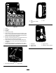
Safety and Instructional Decals Safety decals and instructions are easily visible to the operator and are located near any area of potential danger. Replace any decal that is damaged or lost. Manufacturer's Mark 1. Indicates the blade is identified as a part from the original machine manufacturer. 100-7449 93-6674 1. Pull the lever out to push the machine. 1. Crushing hazard, hand—read the instructions before servicing or performing maintenance. 3.
120-1137 1. Fast 2. Continuous variable setting 3. Slow 120-1122 1. Choke 2. Disengage 3. Engage 4. Power take-off (PTO) 5. Traction drive—to drive in reverse, press the bottom of the traction control pedal rearward and down; to drive forward, press the top of the traction control pedal forward and down. 6. Warning—read the Operator’s Manual. 7. Warning—remove the ignition key and read the instructions before servicing or performing maintenance. 8.
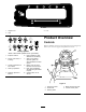
121-0965 3. Low 1. Height-of-cut 2. High Product Overview Controls Become familiar with the controls (Figure 4 through Figure 6) before you start the engine and operate the tractor. Battery Symbols Some or all of these symbols are on your battery 1. Explosion hazard 6. Keep bystanders a safe distance from the battery. 2. No fire, open flame, or smoking. 7. Wear eye protection; explosive gases can cause blindness and other injuries 3. Caustic liquid/chemical burn hazard 4. Wear eye protection 8.
Operation Note: Determine the left and right sides of the machine from the normal operating position. Gasoline and Oil Recommended Gasoline Use unleaded regular gasoline suitable for automotive use (87 pump octane minimum). You may use leaded regular gasoline if unleaded regular is not available. Figure 5 1. Throttle lever 3. Ignition switch 2. Light switch—on/off 4.
Add the correct amount of fuel stabilizer/conditioner to the gasoline. DANGER In certain conditions, gasoline is extremely flammable and highly explosive. A fire or explosion from gasoline can burn you and others and can damage property. Note: A fuel stabilizer/conditioner is most effective when it is mixed with fresh gasoline. To minimize the chance of varnish deposits in the fuel system, use a fuel stabilizer/conditioner at all times.
Operating the Headlights 3. Stop the engine, remove the key, and wait for all moving parts to stop before leaving the operating position. A dash-mounted On/Off switch (Figure 4) controls the headlights. The lights only shine while the engine is running and the switch is On. 4. Pull on the height-of-cut lever on the tractor and move it to the desired position (Figure 9). Operating the Blade Control (PTO) 1 2 The blade control (PTO) engages and disengages power to the electric clutch.
2. Turn the ignition key to the Off position, wait for all moving parts to stop, and remove the key before leaving the operating position. (Figure 11). 1 Using the Safety Interlock System Service Interval: Before each use or daily 2 CAUTION If the safety interlock switches are disconnected or damaged, the tractor could operate unexpectedly, causing personal injury. G018128 3 Figure 10 1. Fast 2. Slow • Do not tamper with the interlock switches. 3.
Testing the Safety Interlock System 1 CAUTION If safety interlock switches are disconnected or damaged, the tractor could operate unexpectedly, causing personal injury. • Do not tamper with the interlock switches. • Check the operation of the interlock switches daily and replace any damaged switches before operating the tractor. • Replace switches every 2 years regardless of whether they are operating properly or not. G006903 Figure 12 1.
Note: This tractor features an automatic brake system that engages whenever you take your foot off the traction control pedal. Note: To reverse the tractor with the blade control (PTO) engaged, deactivate the operating-in-reverse interlock using the KeyChoice switch located in front of and below the seat. Stopping the Tractor 1. Release the traction control pedal. 2. Disengage the blade control (PTO). 3. Turn the ignition key to Off to stop the engine. Figure 13 4. Remove the ignition key from the switch.
• Cut the grass slightly longer than normal to ensure that the cutting height of the mower does not scalp any uneven ground. When cutting grass longer than 6 inch (15 cm) tall, cut the lawn twice to ensure an acceptable appearance. • It is best to cut only about 1/3 of the grass blade. Do not cut more than that unless the grass is sparse or it is late fall when grass grows more slowly. • Alternate the mowing direction to keep the grass standing straight.
Maintenance Note: Determine the left and right sides of the machine from the normal operating position. Recommended Maintenance Schedule(s) Maintenance Service Interval Maintenance Procedure After the first 8 hours • Change the engine oil. Before each use or daily • • • • • Check the engine oil level. Check the safety system. Check the battery electrolyte. Service the blades. Wash the underside of the mower. Every 25 hours • Grease and lubricate the tractor. More often in dusty or dirty conditions.
Lubrication Engine Maintenance Greasing and Lubricating the Tractor Servicing the Engine Oil Service Interval: Every 25 hours—Grease and lubricate the tractor. More often in dusty or dirty conditions. Crankcase Capacity: 1.6 qt. (1.5 l) when you do not change the filter; 1.9 qt. (1.7 l) when you change the filter. Oil Type: Detergent oil (API service SF, SG, SH, SJ, or higher) Viscosity: See the table below. SAE V iscosity Grades How to Grease the Tractor SAE 40 1.
7. Insert the oil dipstick into the fill hole, but do not screw it into the fill hole. 10. Slowly pour approximately 80% of the specified amount of oil into the fill hole (Figure 17). Check the oil level; refer to Checking the Oil Level. 8. Remove the dipstick again and look at the end. If the oil level is low, slowly pour only enough oil into the fill hole to raise the level to the Full mark on the dipstick.
Servicing the Air Cleaner Important: Do not clean the element with pressurized air or liquids, such as solvents, gasoline, or kerosene. Replace the element if it is damaged or cannot be cleaned thoroughly. Service Interval: Every 100 hours—Service the air cleaner filter element (more often in dusty, dirty conditions). Every 200 hours—Replace the air cleaner filter element (more often in dusty, dirty conditions). Servicing the Spark Plugs Service Interval: Every 100 hours—Check the spark plugs.
Fuel System Maintenance Replacing the Fuel Filter Service Interval: Every 100 hours—Replace the fuel filter. Important: Do not install a dirty filter if it is removed from the fuel line. Figure 22 1. Center electrode insulator 1. Park the machine on a level surface and disengage the blade control (PTO). 3. Air gap (not to scale) 2. Side electrode 2. Stop the engine, wait for all moving parts to stop, and remove the key before leaving the operating position. Important: Do not clean the spark plugs.
Electrical System Maintenance WARNING Incorrectly routing the battery cable could damage the tractor and cables, causing sparks. Sparks can cause the battery gasses to explode, resulting in personal injury. Servicing the Battery • Always disconnect the negative (black) battery cable before disconnecting the positive (red) cable. Always keep the battery clean and fully charged. Use a paper towel to clean the battery and battery box.
3. If the electrolyte is low, add the required amount of distilled water; refer to Adding Water to the Battery. 3. Make sure that the vent caps are installed in the battery, and charge it for 1 hour at 25 to 30 amps or 6 hours at 4 to 6 amps. Do not overcharge the battery. DANGER 4. When the battery is fully charged, unplug the charger from the electrical outlet. Battery electrolyte contains sulfuric acid, a deadly poison that can severely burn you and others.
Cooling System Maintenance Blade Maintenance Cleaning the Cooling System Service Interval: Before each use or daily Service Interval: Every 100 hours—Clean the cooling system. To ensure a superior quality of cut, keep the blades sharp. For convenient sharpening and replacement, keep extra blades. Servicing the Blades Use a dry brush to clean grass and accumulated debris from the engine. DANGER 2.
Removing the Mower 1. Park the tractor on a level surface. 2. Disengage the blade control (PTO). 3. Stop the engine, remove the key, and wait for all moving parts to stop before leaving the operating position. 4. Move the height-of-cut lever to the lowest position. 5. Remove the mower belt from the electric clutch pulley (Figure 32). Figure 29 1. Bolt 4. Spindle 2. Retainer 3. Blade 5. Curved washer 4. Inspect all parts; replace any parts that are damaged. Sharpening the Blades 1.
Installing the Mower 1. Park the tractor on a level surface. 2. Disengage the blade control (PTO). 3. Stop the engine, remove the key, and wait for all moving parts to stop before leaving the operating position. 4. Slide the mower deck under the machine. 5. Install the mower belt onto the electric clutch pulley (Figure 32). 6. Move the height-of-cut lever to the lowest position. G020051 1 2 3 7. Lift the rear of the mower deck, and guide the hanger brackets over the rear lift rod (Figure 34).
Leveling the Mower from Side-to-Side The mower blades must be level from side to side. Check the side-to-side level whenever you install the mower or look for an uneven cut on your lawn. Before you level the mower, set the air pressure in the tires to the recommended level; refer to Checking the Tire Pressure. 4 1. Park the tractor on a level surface. 1 3 2. Disengage the blade control (PTO). 6 3.
3. Stop the engine, remove the key, and wait for all moving parts to stop before leaving the operating position. 4. Check and adjust the side-to-side blade level if you have not checked the setting; refer to Leveling the Mower from Side-to-Side. 5. Move the height-of-cut lever into one of the middle notches. 6. Measure from the top of the front blade to the flat surface and the tip of the rear blade to the flat surface (Figure 38).
Servicing the Headlights Cleaning The headlights use an 1156, automotive-type bulb. Washing the Underside of the Mower Removing the Bulb 1. Open the hood. Service Interval: Before each use or daily 2. Disconnect the wire connectors from both of the bulb holder terminals. Wash the underside of the mower to prevent grass buildup for improved clipping dispersal. 3. Rotate the bulb holder 1/4 turn clockwise and remove it from the reflector (Figure 42). 1. Park the tractor on a level surface. 2.
Storage WARNING A broken or missing washout fitting could expose you and others to thrown objects or to blade contact. Contact with the blade or thrown debris contact may cause injury or death. 1. Disengage the blade control (PTO). 2. Stop the engine, wait for all moving parts to stop, and remove the key before leaving the operating position. 3. Remove grass clippings, dirt, and grime from the external parts of the entire tractor, especially the engine.
10. Disconnect the negative battery cable. Clean the battery and battery terminals. Check the electrolyte level and charge it fully; refer to Servicing the Battery. Leave the negative battery cable disconnected from the battery during storage. Important: The battery must be fully charged to prevent it from freezing and being damaged at temperatures below 32°F (0°C). A fully charged battery can be stored during the winter without recharging. 11. Check and tighten all bolts, nuts, and screws.
Troubleshooting Problem The starter does not crank. The engine will not start, starts hard, or fails to keep running. Possible Cause 1. The blade control (PTO) is engaged. 1. Disengage the blade control (PTO). 2. The transmission drive control is in the Push position. 3. The battery is dead. 4. The electrical connections are corroded or loose. 5. A fuse is blown. 6. A relay or switch is damaged. 2. Move the transmission drive control to the Operate position. 3. Charge the battery. 4.
Problem The tractor does not drive. The mower is cutting unevenly. Possible Cause Corrective Action 1. The drive control is in the Push position. 1. Move the drive control to the Operate position. 2. The traction belt is worn, loose, or broken. 3. The traction belt is off of the pulley. 2. Contact an Authorized Service Dealer. 1. The tire pressure is incorrect. 1. Set the tire pressure. 2. The mower is not level. 2. Level the mower from side-to-side and front-to-rear. 3.
Schematics Wiring Diagram (Rev.
Intl Dist List Distributor: Atlantis Su ve Sulama Sisstemleri Lt Balama Prima Engineering Equip. B-Ray Corporation Casco Sales Company Ceres S.A. CSSC Turf Equipment (pvt) Ltd. Cyril Johnston & Co. Equiver Femco S.A. G.Y.K. Company Ltd. Geomechaniki of Athens Guandong Golden Star Hako Ground and Garden Hako Ground and Garden Hayter Limited (U.K.
The Toro Warranty Conditions and Products Covered Owner Responsibilities The Toro Company and its affiliate, Toro Warranty Company, pursuant to an agreement between them, jointly promise to the original purchaser* to repair the Toro Products listed below if defective in materials or workmanship. You must maintain your Toro Product by following the maintenance procedures described in the Operator's Manual. Such routine maintenance, whether performed by a dealer or by you, is at your expense.