Form No. 3353–243 420 and 430 Garden Tractor Model No. 72201—Serial No. 250000001 and Up Model No. 72202—Serial No. 250000001 and Up Operator’s Manual Register your product at www.Toro.
Warning Checking the Tractor Lubrication . . . . . . . . . . . . Learn to Operate the Tractor . . . . . . . . . . . . . . . . Test Driving the Tractor . . . . . . . . . . . . . . . . . . . . Checking the Safety System . . . . . . . . . . . . . . . . Operation . . . . . . . . . . . . . . . . . . . . . . . . . . . . . . . . . . Think Safety First . . . . . . . . . . . . . . . . . . . . . . . . Controls for Model 72201 . . . . . . . . . . . . . . . . . . Controls for Model 72202 . . . . . . . . . . . . . . .
Safety damage. Although Toro designs and produces safe products, you are responsible for operating the product properly and safely. This machine meets or exceeds the B71.1–2003 specifications of the American National Standards Institute, in effect at the time of production. However, improper use or maintenance by the operator or owner can result in injury.
• Disengage blades when not mowing. Stop the engine and what for all parts to come to a complete stop before cleaning the machine, removing the grass catcher or unclogging the discharge chute. • Do not mow near drop-offs, ditches, or embankments. The machine could suddenly turn over if a wheel goes over the edge of a cliff or ditch, or if an edge caves in. • Operate the machine only in daylight or good artificial light.
• Use only an approved gasoline container. Toro Riding Mower Safety • Never remove the gas cap or add fuel when the engine is running. Allow the engine to cool before refueling. • Never refuel the machine indoors. The following list contains safety information specific to Toro products or other safety information that you must know that is not included in the ANSI standards.
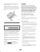
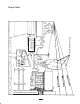
Slope Chart Fold along appropriate line Example: Compare slope with folded edge. Align this edge with a vertical surface (Tree, Building, Fence post, pole, etc.
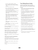
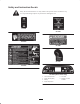
Safety and Instruction Decals Safety decals and instructions are easily visible to the operator and are located near any area of potential danger. Replace any decal that is damaged or lost. 112168 92-6726 83-6620 99-2985 99-5339 93-0302 106-9871 (Model 72202 only) 1. 2. 3. 4. 9 Cruise control, locked Power Take-off (PTO) Battery Engine oil pressure 5. Fuel level 6. Mowing in reverse enabled.
99-8036 (Model 72201 only) 1. Mowing in reverse enabled. 2. Battery 3. Engine oil pressure 4. Power Take-off (PTO) 92-6721 104-4163 1. Explosion hazard 2. No fire, open flames, or smoking. 3. Caustic liquid/chemical burn hazard 92-6720 1. Pull the knob out to start the PTO. 2. Push the knob in to stop the PTO. 10 4. Wear eye protection 5. Read the Operator’s Manual. 6. Keep bystanders a safe distance from the battery.
Battery Symbols Some or all of these symbols are on your battery. 1. Explosion hazard 2. No fire, open flames, or smoking. 3. Caustic liquid/chemical burn hazard 4. Wear eye protection; explosive gases can cause blindness and other injuries 5. Wear eye protection 6. Read the Operator’s Manual. 7. Keep bystanders a safe distance from the battery. 8. Battery acid can cause blindness or severe burns. 9. Flush eyes immediately with water and get medical help fast. 10. Contains lead; do not discard.
Gasoline and Oil Recommended Gasoline Warning Use UNLEADED Regular Gasoline suitable for automotive use (85 pump octane minimum). Leaded regular gasoline may be used if unleaded regular is not available. Gasoline is harmful or fatal if swallowed. Long–term exposure to vapors can cause serious injury and illness. Important Never use methanol, gasoline containing methanol, or gasohol containing more than 10% ethanol because the fuel system could be damaged. Do not mix oil with gasoline.
Setup Note: Determine the left and right sides of the machine from the normal operating position. Loose Parts Note: Use the chart below to verify all parts have been shipped. Description Qty. Use Bolt, 1/4 x 3/4 inch 2 Hex Nut, 1/4 inch 2 Key 1 Use in ignition switch. Operator’s Manual 1 Read before operating tractor Riding Mower Safety Video 1 View before operating tractor Checking the Tire Pressure Activating and installing the battery 4.
Learn to Operate the Tractor Note: Make sure the vent caps are installed in battery. 7. Charge the battery for 1 hour at 10 amps or 2 hours at 5 amps. Learn how to operate the tractor. Read the Operation section starting on page 15. 8. When the battery is fully charged, unplug the charger from the electrical outlet, then disconnect the charger leads from the battery posts (Fig. 3). Test Driving the Tractor 1. Fill the tank with unleaded regular gasoline; Gasoline and Oil, page 12.
Controls for Model 72202 Operation Become familiar with all the controls (Fig. 2) before you start the engine and operate the machine. Think Safety First 1 Please carefully read all the safety instructions. Knowing this information could help you, your family, pets or bystanders avoid injury. 13 6 10 9 11 2 7 Controls for Model 72201 3 12 8 Become familiar with all the controls (Fig. 1) before you start the engine and operate the machine.
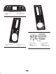
Releasing the Parking Brake 2 1. Push down on the brake pedal (Fig. 3). The parking brake lever should release. 5 3 2. Gradually release the brake pedal. 4 1 6 1 m–6523 Figure 4 1. PTO—Off 2. Choke–On 3. Choke–Off 2 4. Throttle lever 5. Fast 6. Slow 1 2 m–6516 3 Figure 3 1. Brake pedal 2. Parking brake lever 4 1208 Starting and Stopping the Engine Figure 5 1. Off 2. Lights Starting the Engine 3. Run 4. Start 1. Sit down on the seat. Stopping the Engine 2.
Understanding the Safety Interlock System Operating the Power Take Off (PTO) The safety interlock system is designed to prevent the engine from starting unless: The power take off (PTO) engages and disengages power to the electric clutch. • You are sitting on the seat. While the ignition key is in run or lights position and the power take off (PTO) is engaged on, the PTO light, in the Indicator Module, will be on.
will illuminate. Move the foot pedal to reverse. You should hear an audible click indicating the PTO is deactivated and the PTO light should turn off. 7. With the parking brake released, turn the ignition switch to RUN without starting the engine. Pull the PTO switch to on. Turn the KeyChoice key and release. The Operating-in-Reverse warning light should illuminate. Move the foot pedal to reverse. The PTO and PTO light on the dash should remain on. Push the PTO switch to off.
Indicator Control Module PTO (Power Take Off) The indicator control module (Fig. 10) contains lights for: The PTO (power take off) light will be on when the ignition key is in the run or lights positions and the PTO (power take off) is engaged on. When this light is on it is a reminder; the starter will not crank and turn off the PTO before getting off.
2. Push the lift switch in the up direction to raise the attachment lift (Fig. 13). This will lift and hold the attachment in the up, or raised position. To slow down, release the pressure on the traction control pedal. Important To avoid transmission damage, always release the parking brake before moving the traction control pedal. Lowering Attachments 1. Turn key to the on or run position (Fig. 13). 2. Push the lift switch in the down direction to lower the attachment lift (Fig. 13).
2 1 1 1208 Figure 16 1. Lights m–6531 Positioning the Tilt Steering Wheel Figure 14 1. Lift lever 2. Button The steering wheel has four tilt locations. Position the steering wheel where you have the best control of the machine and are most comfortable. Positioning the Seat 1. Lift the tilt lever to release the lock (Fig. 17). The seat can move forward and backward. Position the seat where you have the best control of the machine and are most comfortable. 2.
Engaging the Cruise Control 1 1. Begin driving tractor: Refer to Driving Forward or Backward, page 19. While holding your foot steady on the traction control, push the cruise control switch (Fig. 18) to the lock–set position. 3 2 1 M–4566 Figure 19 2 1. Operate position 2. Push position 1238 Figure 18 1. Lock–Set 2. Unlock–Off 2. This locks the traction control in position and your foot can then be removed from the traction control. A constant ground speed will be maintained.
Maintenance Recommended Maintenance Schedule Maintenance Service Interval After First 8 Hours Each Use Maintenance Procedure • Change oil1 • • • • • Check oil level Check safety system Check brake Clean air intake screen Check battery electrolyte Every 25 Hours • Clean foam air cleaner1 • Check tire pressure Every 50 Hours • Grease chassis1 • Check belts for wear/cracks • Clean paper air cleaner Every 100 Hours • • • • Every 200 Hours • Change oil filter1 • Replace paper air cleaner Check spark
Servicing the Engine Oil Change the oil after the first 8 operating hours and every 100 operating hours thereafter. Oil Type: Detergent oil (API service SF, SG, SH or SJ) 1 Crankcase Capacity: 2 • when the oil filter is not removed, 51 oz. (1.5 l) 3 • when the oil filter is removed, 58 oz. (1.7 l) Viscosity: See the table below. m–4291 m–6526 USE THESE SAE VISCOSITY OILS Figure 20 1. Oil dipstick 2. Filler tube 3. Dipstick end Changing and Draining the Oil 1.
7. Slowly pour approximately 80% of the specified oil into the filler cap (Fig. 20). Refer to Servicing the Engine Oil, page 24. 3. Clean debris and grass from the parts. 4. Install the air intake screen, cylinder covers, and fan housing. 8. Check the oil level; refer to Checking the Oil Level, page 24. 1 9. Slowly add additional oil to bring it to the full mark. Changing the Oil Filter 2 Replace the oil filter every 200 hours or every other oil change.
3 5 4 1 2 2 6 m–4289 Figure 24 1. Cover 2. Foam element 3. Paper element 4. Wing nut 5. Air cleaner base 6. Latches ÄÄÄÄÄÄ ÄÄÄÄÄÄ ÄÄÄÄÄÄ ÄÄÄÄÄÄ ÄÄÄÄÄÄ ÄÄÄÄÄÄ 1 m–4293 Figure 25 1. Paper element 2. Rubber seal Cleaning the Foam Element Installing the Foam and Paper Elements 1. Wash the foam element in liquid soap and warm water (Fig. 24). When the element is clean, rinse it thoroughly.
3. Push the wire(s) onto the spark plug(s) (Fig. 26). Greasing and Lubrication 1 Grease the machine after every 50 operating hours or yearly, whichever occurs first. Grease more frequently when operating conditions are extremely dusty or sandy. 2 Grease Type: General-purpose grease. How to Grease M–4294 1. Disengage the power take off (PTO), set the parking brake, and turn the ignition key to off. Remove the ignition key. Figure 26 1. Spark plug wire installed 2. Spark plug 2.
Checking the Tire Pressure 3. To adjust the brake remove the cotter pin and loosen the brake adjusting nut slightly (Fig. 30). Maintain the air pressure in the front and rear tires as specified. Check the pressure at the valve stem after every 25 operating hours or monthly, whichever occurs first (Fig. 29). Check the tires when they are cold to get the most accurate pressure reading. 4. Carefully insert a 0.015 inch (0.38 mm) feeler gauge between the outer brake pad and rotor disk (Fig. 30). 5.
Servicing the Fuel Filter 2. Stop the engine, remove the key, and wait for all moving parts to stop before leaving the operating position. Replace the fuel filter after every 100 operating hours or yearly, whichever occurs first. 3. Close the fuel shut–off valve at the fuel tank (Fig. 31). Replacing the Fuel Filter Never install a dirty filter if it is removed from the fuel line. 1. Disengage the PTO and set the parking brake. 2.
Servicing the Fuses 5. The front measurement should be less than the rear, as specified. Service Interval/Specification The electrical system is protected by fuses. It requires no maintenance, however, if a fuse blows check component/circuit for malfunction or short. To replace fuses pull up on the fuse (Fig. 34) to remove or replace it.
Servicing the Battery 5. Push and rotate the bulb counterclockwise until it stops (approx. 1/4 turn) and remove bulb from the bulb holder (Fig. 36). Warning 5 5 CALIFORNIA 1 Proposition 65 Warning 3 Battery posts, terminals, and related accessories contain lead and lead compounds, chemicals known to the State of California to cause cancer and reproductive harm. Wash hands after handling. 4 2 Service Interval/Specification 4 Always keep the battery clean and fully charged.
2. Stop the engine, remove the key, and wait for all moving parts to stop before leaving the operating position. 1 3. Open the hood and locate the battery. 4. Remove the right side panel for clearance when removing battery (Fig. 38). Remove the screws and lift up the panel to clear the pin and slide panel tabs out from the steering tower. 2 5 5. Disconnect the negative (black) ground cable from the battery post (Fig. 37). 3 6. Lift the red cover up from the positive cable.
Important Always keep the battery fully charged (1.265 specific gravity). This is especially important to prevent battery damage when the temperature is below 32°F (0°C). Danger Battery electrolyte contains sulfuric acid which is a deadly poison and causes severe burns. 1. Remove the battery from the chassis; refer to Removing the Battery, page 31. • Do not drink electrolyte and avoid contact with skin, eyes or clothing. Wear safety glasses to shield your eyes and robber gloves to protect your hands.
7 BU 5 BU (MOMENTARY) 8 6 Y BATTERY OIL OVER RIDE PTO #194 LAMP #194 LAMP #194 LAMP #194 LAMP BLK OR GN T W F E D C B WARNING LIGHT HARNESS A PK SW2B (CRUISE DISENGAGE SWITCH) 1 SWITCH OPENS WHEN BRAKE IS DEPRESSED 2 T BLK BLK PK 2 PK K3 (CRUISE RELAY) CRUISE MAGNET BLK OR GN T W PK BLK BU 2 5 3 5 AND 6 CONNECTED 1 4 3 GN BLK – HOUR METER GYW BN PK BU GN GN BLK SWITCH OPENS WHEN HYDRO PEDAL IS MOVED TO REVERSE BLK T P2 Y PK OR SW1 (SEAT SWITC
2 T 7 BU 5 BU (MOMENTARY) 8 6 2 Y #194 LAMP #194 LAMP #194 LAMP CRUISE BATTERY #194 LAMP #194 LAMP #194 LAMP LOW FUEL OIL OVER RIDE PTO E G H D C B BLK F OR GY BU GN T W WARNING LIGHT HARNESS A PK BU BLK OR GY BU GN T W PK 6 BLK K3 (CRUISE RELAY) CRUISE MAGNET BU BLK SW2B (CRUISE DISENGAGE SWITCH) 1 SWITCH OPENS WHEN BRAKE IS DEPRESSED BLK BLK PK 3 2 5 BU 1 5 AND 6 CONNECTED 3 PK 4 1 4 3 CRUISE SWITCH OPERATION OFF NO CONNECTION ON 3 AND 2 CONNECTED
Cleaning and Storage D. Restart engine and run it until it stops. 1. Disengage the power take off (PTO), set the parking brake, and turn the ignition key to off. Remove the ignition and KeyChoice keys. E. Choke or prime the engine. Start and run engine until it will not start. Operate primer, if equipped on machine, several times to ensure fuel remains in primer system. 2. Remove grass clippings, dirt, and grime from the external parts of the entire machine, especially the engine.
Troubleshooting Problem Starter does not crank Engine g will not start,, starts hard,, or f il to fails t keep k running. i Engine g loses power. Engine g overheats. Possible Causes Corrective Action 1. Blade control (PTO) is ENGAGED. 1. Move blade control (PTO) to DISENGAGED. 2. Parking brake is not on. 2. Set parking brake. 3. Operator is not seated. 3. Sit on the seat. 4. Battery is dead. 4. Charge the battery. 5. Electrical connections are corroded or loose. 5.
Problem Abnormal vibration. Machine does not drive. Possible Causes Corrective Action 1. Engine mounting bolts are loose. 1. Tighten engine mounting bolts. 2. Loose engine pulley, idler pulley, or blade pulley. 2. Tighten the appropriate pulley. 3. Engine pulley is damaged. 3. Contact Authorized Service Dealer. 1. Drive control is in the push position. 1. Move drive control to the operate position. 2. Traction belt is worn, loose or broken. 2. Contact Authorized Service Dealer. 3.
Consumer Lawn Tractors and Lawn & Garden Tractors The Toro Total Coverage Guarantee A Two-Year Full Warranty (Limited Warranty for Commercial Use) Conditions and Products Covered The Toro Company and its affiliate, Toro Warranty Company, pursuant to an agreement between them, jointly promise to repair any Toro Product used for normal residential purposes* if defective in materials or workmanship.