
Service Manual


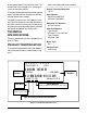

310-3000 IHT 1
INTRODUCTION
The purpose of this manual is to provide infor-
mation useful in servicing the Hydro-Gear 310-
3000 Integrated Hydrostatic Transaxle (IHT). This
manual includes transaxle general description,
hydraulic schematic, technical specifications,
product identification, safety, troubleshooting,
maintenance, and repair procedures.
The transaxle normally will not require servicing
during the life of the vehicle in which it is installed.
Should other servicing be required, the transaxle
will need to be thoroughly cleaned before begin-
ning most procedures.
Please refer to the instructions titled “How to Use
This Manual” in the Repair Section for an expla-
nation of the layout of the disassembly, inspec-
tion, and reassembly portions of this manual.
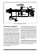
GENERAL DESCRIPTION
The 310-3000 is a self contained unit designed
for the transfer and control of power. It provides
an infinitely variable speed range between zero
and maximum in both forward and reverse
modes of operation.
This transaxle uses a variable displacement
pump with a maximum displacement of 10 cc
per revolution, and motor with a fixed displace-
ment of 21cc per revolution. The variable dis-
placement pump features a cradle swashplate
with a direct-proportional displacement control.
Reversing the direction of the swashplate re-
verses the flow of oil from the pump and thus re-
verses the direction of the motor output rotation.
The pump and motor are of the axial piston de-
sign and utilize spherical nosed pistons which
are held against a thrust race by internal com-
pression springs.
The 310-3000 has a self contained fluid supply
and an internal filter. The fluid is drawn through
the internal reservoir and feeds the fixed dis-
placement gerotor charge pump. Excess fluid in
the charge circuit is discharged over the charge
relief valve and dumps back to case. Charge
check valves in the center section are used to
control the makeup flow of the fluid to the low pres-
sure side of the loop.
The transaxle is filled and tested at the factory
and should not require fluid or filter changes un-
less the fluid becomes contaminated.
A cam style, block lifting bypass is utilized in the
310-3000 to permit moving the vehicle for short
distance at a maximum of 2 m.p.h. without start-
ing the engine.
WARNING
Actuating the bypass will result in the
loss of hydrostatic braking capacity. The
machine must be stationary on a level
surface and in neutral when actuating
the bypass.
The 310-3000 utilizes an in-line floating disc
brake controlled by a "cam" style actuating arm.
SECTION 1. DESCRIPTION AND OPERATION