
Service Manual


2
310-3000 IHT
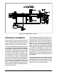
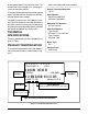
Figure 1. 310-3000 Hydraulic Schematic
HYDRAULIC SCHEMATIC
Figure 1 provides an illustration of the hydraulic
oil circuit. The oil supply for the hydraulic system
of the 310-3000 IHT is also utilized for the lubri-
cation of the planetary differential drive gears.
The input shaft and pump cylinder block are turned
in one direction only by the engine/drive belt/pul-
ley combination. Output of the oil flow is controlled
by the direction and amount that the swashplate
is angled. As the pump pistons compress they
force the oil to flow through one of two passage-
ways (forward or reverse) in the center section
(or valve body) to the motor cylinder block and
motor shaft. Since the motor has a fixed displace-
ment angle it is forced to turn with the flow of oil.
As the angle of the swashplate is increased the
amount of oil being pumped will increase and
cause a higher RPM output of the motor. Revers-
ing the angle of the pump swashplate will reverse
the direction of oil flow.
During the operation of the transaxle, fluid is “lost”
from the hydraulic loop through leak paths de-
signed into the product for lubrication purposes
(around pistons, under the rotating cylinder
blocks, etc.). This “lost” fluid returns to the trans-
mission housing and must be made up in the
loop. A charge pump is included on the 310-3000
IHT to supply this makeup flow. The make up flow
is controlled (or directed) by the check valves.
Each check valve will either be held opened or
closed (depending upon the direction of vehicle
operation) by the system operating pressure
(closed) or by charge pressure (open) from the
charge pump.
The charge pump maintains a continuous flow of
oil as long as the input shaft is turning. All of the
oil being pulled into the charge pump first must
pass through an internal filter. Any oil not needed
by the transmission for make up flow is