
Service Manual


Section
I
5003
-
5010
TRANSMISSIONS
DESCRIPTION
The 5003 and
5010
transmissions are readily iden-
The differential
is
of
the spur pinion type. On all
tified
by
their removable steel side covers which are
original equipment transmissions, the ring gear
is
an
bolted to a one piece cast iron case. The transmissions
integral part of the differential case. The service re-
are of the sliding gear type. and provide three speeds
placement, however, consists of a case and gear as-
forward and one speed in reverse.
sembly in which the gear
is
bolted to the differential
case.
All
shafts operate on needle or ball bearings sup-
ported
by
the steel side covers.
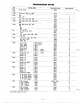
RATIOS
1st gear
...............
66.8
to
1
2nd gear
..............
42.4
to
1
3rd
gear
...............
24.6
to
1
Reverse
...............
51.5
to
1
REMOVAL .AND REPLACEMENT
Removal:
Remove any mid-mounted or trailing attachment
Remove three bolts at each transmission side cover
which might interfere with transmission removal.
and frame side rail. Move transmission assembly
Provide-some support under the tractor frame ahead
away from the tractor. Remove the wheels and hubs,
of the transmission.
clutch and idler arm assembly, and transmission in-
put pulley.
Remove the seat, fender and tool box assembly
if
so
equipped, belt guard, belt, and clutch rod. Discon-
Drain lubricant and clean case as necessary
be-
nect the
lift
cable and remove the hitch.
fore disassembling.
Installation:
Install clutch and
idler
arm assembly, brake rod, Install drive belt and belt guard. Connect clutch
and input pulley. Install wheels and hubs and move rod. Lay lift cable in place along top
of
transmission,
assembly into place on the tractor. Install three bolts
through holes in each transmission side cover and Install fender and tool box assembly
if
so
securely. neath tractor frame.
install hitch and connect lift cable.
corresponding holes in frame
side
rails. Tighten nuts equipped, and install seat. Remove support from
be-
-5-