Form No. 3366-401 Rev B TimeCutter® ZS 4200 and ZS 5000 Riding Mower Model No. 74386—Serial No. 311000001 and Up Model No. 74387—Serial No. 311000001 and Up To register your product or download an Operator's Manual or Parts Catalog at no charge, go to www.Toro.com.
This machine is a ride-on, rotary-blade lawnmower intended to be used by homeowners in residential applications. It is primarily designed for cutting grass on well-maintained lawns. It is not designed for cutting brush, mowing grass and other growth alongside highways, or for agricultural uses. Introduction This product complies with all relevant European directives, for details please see the separate product specific Declaration of Conformity (DOC) sheet. You may contact Toro directly at www.Toro.
This manual uses two other words to highlight information. Important calls attention to special mechanical information and Note emphasizes general information worthy of special attention. Electrical System Maintenance................................ 36 Charging the Battery........................................... 36 Servicing the Fuses ............................................. 37 Drive System Maintenance ..................................... 38 Checking the Tire Pressure .............................
Safety ◊ lack of awareness of the effect of ground conditions, especially slopes; ◊ incorrect hitching and load distribution. Safe Operation Practices for Ride-on (riding) Rotary Lawnmower Machines Preparation • While mowing, always wear substantial footwear and long trousers. Do not operate the equipment when barefoot or wearing open sandals. • Thoroughly inspect the area where the equipment is to be used and remove all objects which may be thrown by the machine. • Warning-Fuel is highly flammable.
– use low speeds on slopes and during tight turns; • Reduce the throttle setting during engine run-out and, if the engine is provided with a shut-off valve, turn the fuel off at the conclusion of mowing. • Lightning can cause severe injury or death. If lightning is seen or thunder is heard in the area, do not operate the machine; seek shelter. – stay alert for humps and hollows and other hidden hazards; • Use care when pulling loads. – Use only approved drawbar hitch points.
Slope Operation Vibration • Do not mow slopes greater than 15 degrees. • Do not mow near drop-offs, ditches, steep banks, or water. Wheels dropping over edges can cause rollovers, which may result in serious injury, death, or drowning. • Do not mow slopes when grass is wet. Slippery conditions reduce traction and could cause sliding and loss of control. • Do not make sudden turns or rapid speed changes. • Use a walk behind mower and/or a hand trimmer near drop-offs, ditches, steep banks, or water.
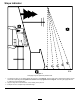
Slope Indicator G011841 Figure 3 This page may be copied for personal use. 1. The maximum slope you can safely operate the machine on is 15 degrees. Use the slope chart to determine the degree of slope of hills before operating. Do not operate this machine on a slope greater than 15 degrees. Fold along the appropriate line to match the recommended slope. 2. Align this edge with a vertical surface, a tree, building, fence pole, etc. 3. Example of how to compare slope with folded edge.
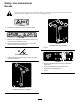
Safety and Instructional Decals Safety decals and instructions are easily visible to the operator and are located near any area of potential danger. Replace any decal that is damaged or lost. 114-1606 1. Entanglement hazard, belt—keep all guards in place. 93-7009 1. Warning—don't operate the mower with the deflector up or removed; keep the deflector in place. 2. Cutting/dismemberment hazard of hand or foot, mower blade—stay away from moving parts. 99-3943 For Models with 50 Inch Decks 1.
110-6691 1. Thrown object hazard—keep bystanders a safe distance from the machine. 2. Thrown object hazard, mower—do not operate without the deflector, discharge cover, or grass collection system in place. 112-9840 1. Read the Operator's Manual. 3. Cutting/dismemberment of hand or foot—stay away from moving parts. 3. Remove the ignition key and read the instructions before servicing or performing maintenance. 2. Height of cut 119-8814 1. Parking position 4. Neutral 2. Fast 3. Slow 5.
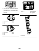
Battery Symbols Some or all of these symbols are on your battery 1. Explosion hazard 6. Keep bystandersa safe distance from the battery. 2. No fire, open flame, or smoking. 7. Wear eye protection; explosive gases can cause blindness and other injuries 3. Caustic liquid/chemical burn hazard 4. Wear eye protection 8. Battery acid can cause blindness or severe burns. 9. Flush eyes immediately with water and get medical help fast. 5. Read the Operator's Manual. 120-5470 1. Height-of-cut 120-5465 1.
120-5468 2. Fast speed 1. Slow speed 119-8873 Certain models only 1. Fast 5. Power take-off (PTO), Blade control switch on some models 2. Continuous variable setting 6. Blade control switch—Off 3. Slow 4. Choke 7.
119-8872 119-8872 Certain models only 1. Fast 5. Power take-off (PTO), Blade control switch on some models 2. Continuous variable setting 6. Blade control switch—On 3. Slow 4. Choke 7.
120-2239 1. Warning—read the Operator's Manual. 5. Warning—do not use split ramps, use a full ramps when transporting machine. 2. Warning—read the instructions before servicing or performing maintenance; move the motion control levers to the park (brake) position, remove the ignition key and disconnect the spark plug wire. 6. Loss of traction/control hazard, slopes—loss of traction/control on a slope, disengage the blade control switch (PTO), proceed off the slope slowly. 3.
Product Overview 4 3 5 9 6 G01491 1 8 2 7 10 1 11 2 12 Figure 4 Models with 42 inch decks 1. Deflector 7. Footrest 4. Height of cut lever 10. Engine 2. Rear drive wheel 5. Operator seat 8. Fuel tank cap 11. Engine guard 3. Motion control levers 6. Smart Speed™ lever 9. Control panel 12. Front caster wheel 3 4 2 11 10 12 G014910 5 1 9 6 15 14 13 7 8 Figure 5 Models with 50 inch decks 1. Foot assist lever 9. Footrest 5. Smart Speed™ lever 13. Deflector 2.
Motion Control Levers and Park Position Controls Become familiar with all of the controls in Figure 4, Figure 5, and Figure 6 before you start the engine and operate the machine. The motion control levers are speed sensitive controls of independent wheel motors. Moving a lever forward or backward turns the wheel on the same side forward or in reverse; wheel speed is proportional to the amount the lever is moved.
Height-of-Cut Lever Operation The height of cut lever allows the operator to lower and raise the deck from the seated position. When the lever is moved up, toward the operator the deck is raised from the ground and when moved down, away from the operator it is lowered toward the ground. Only adjust the height of cut while machine is not moving (Figure 21). Note: Determine the left and right sides of the machine from the normal operating position.
DANGER In certain conditions during fueling, static electricity can be released causing a spark which can ignite the gasoline vapors. A fire or explosion from gasoline can burn you and others and can damage property. • Always place gasoline containers on the ground away from your vehicle before filling. • Do not fill gasoline containers inside a vehicle or on a truck or trailer bed because interior carpets or plastic truck bed liners may insulate the container and slow the loss of any static charge.
• The blades are disengaged. Filling the Fuel Tank • The motion control levers are in the park position. Make sure the engine is shut off and the motion controls are in the park position. Tank maximum capacity is 2.9 gallons. The safety interlock system also is designed to stop the engine whenever the control levers are out of the park position and you rise from the seat. Important: Do Not overfill fuel tank. Fill the fuel tank to the bottom of the filler neck.
Important: Do Not overfill fuel tank. Fill the fuel tank to the bottom of the filler neck. The empty space in the tank allows the fuel to expand. Overfilling may result in fuel leakage or damage to the engine or emission system. 6 2 3. Install the fuel tank cap securely and tighten until it “clicks”. Wipe up any gasoline that may have spilled.
2 3 2 7 1 4 5 1 6 G014904 G014903 Figure 15 1. Control panel 2. Blade control switch—On position Figure 14 1. Control panel 5. Run 2. Ignition key—run position 6. Start 3. Ignition key—start position 7. Choke control Disengaging the Blades 4. Off Push down on the blade control switch to move it to the Off position and disengage the blades (Figure 16). 5. After the engine starts, push down on the Choke control (Figure 14).
to the center, unlocked position. Try starting the engine; the engine should not crank. Repeat with the other motion control lever. 3. While sitting on the seat, move the blade control switch to Off, and lock the motion control levers in the park position. Start the engine. While the engine is running, engage the blade control switch, and rise slightly from the seat; the engine should stop. 4.
Backward 1. Move the motion control levers to neutral and outward to the park position; disengage the blade control switch. 1. Move the levers to the center, unlocked position. 2. To go backward, look behind you and down as you slowly pull the motion control levers rearward (Figure 20). WARNING Removing your hands from the motion control levers while the machine is in motion can result in a loss of control causing harm to you or bystanders.
3 1 2 1 G015319 G014477 Figure 22 Figure 21 1. Height-of-cut lever 1. Adjustment bolt 3. 115 mm (4.5 inch), Transport position 2. Move the seat to the desired position and tighten the bolts. 2. Height-of-cut positions Models with 50 inch Decks 1. Pull up and inward on the lever to move it to the desired cutting position. While sitting in the operator’s position, raise the seat adjustment lever slightly and move the seat forward or backward to the desired position (Figure 23). 2.
1 5. Lower the seat and move the motion control levers inward to the neutral position and turn the ignition key to the run position. Do not start the machine. 2 3 4 The machine is now able to be pushed by hand. 2 3 G014970 Figure 24 1. Control arm shaft 3. Slotted, upper hole 2. Control lever 4. Bolt 1 3. Repeat the adjustment for the opposite control lever. Adjusting the Tilt The motion control levers can be tilted fore or aft for maximum operator comfort. G014479 1.
G009660 DANGER 1 Without the grass deflector, discharge cover, or complete grass catcher assembly mounted in place, you and others are exposed to blade contact and thrown debris. Contact with rotating mower blade(s) and thrown debris will cause injury or death. 2 3 • Never remove the grass deflector from the mower because the grass deflector routes material down toward the turf. If the grass deflector is ever damaged, replace it immediately. 4 5 • Never put your hands or feet under the mower.
Installing the Discharge Cover for Mulching Converting to Side Discharge (For Models with 50 Inch Decks) 1. Park the machine on a level surface and disengage the blade control switch. The mower deck and mower blades shipped with this machine were designed for optimum mulching performance. Side discharge performance can be improved by replacing the mulching blades with standard cutting blades obtained from your local authorized Toro dealer.
1 1 2 2 4 3 3 G015321 Figure 31 1. Bolt (5/16 x 3/4 inch) 3. Lock nut (5/16 inch) 2. Cutoff baffle 1 10. Torque the fasteners to 14-18 ft-lb (7-9 N-m). 11. Lower the grass deflector over the discharge opening. G006475 Important: Ensure the mower has a hinged grass deflector that disperses clippings to the side and down toward the turf, while in side discharge mode. Figure 30 1. Right baffle 3. Discharge opening 2. Curved washer and knob 4.
Long Grass mower free from uncut grass, which allows air to be drawn into the mower. If the grass is ever allowed to grow slightly longer than normal, or if it contains a high degree of moisture, raise the cutting height higher than usual and cut the grass at this setting. Then cut the grass again using the lower, normal setting.
Maintenance Note: Determine the left and right sides of the machine from the normal operating position. Recommended Maintenance Schedule(s) Maintenance Service Interval Maintenance Procedure After the first 8 hours • Change the engine oil. Before each use or daily • • • • • • Check the safety interlock system. Check the engine oil level. Clean the air intake screen. Check the cutting blades. Inspect the grass deflector for damage Clean the mower housing.
Premaintenance Procedures Lubrication Raising the Seat Service Interval: Every 25 hours—Grease all lubrication points. Greasing the Bearings Make sure the motion control levers are locked in the park position. Lift the seat forward. Grease Type: No. 2 General Purpose Lithium Base Grease The following components can be accessed by raising the seat: 1. Park the machine on a level surface and disengage the blade control switch. • Serial plate 2.
Engine Maintenance 4. Connect a grease gun to each fitting (Figure 32 and Figure 33). Pump grease into the fittings until grease begins to ooze out of the bearings. Servicing the Air Cleaner 5. Wipe up any excess grease. Note: Service the air cleaner more frequently (every few hours) if operating conditions are extremely dusty or sandy. Removing the Element 1. Park the machine on a level surface and disengage the blade control (PTO). 2.
1. Lightly tap the element on a flat surface to remove dust and dirt. 2. Inspect the element for tears, an oily film, and damage to the seal. 1. Park the machine on a level surface, disengage the blade control switch, stop the engine, engage parking brake, and remove the key. 2. Make sure the engine is stopped, level, and is cool so the oil has had time to drain into the sump. 3. To keep dirt, grass clippings, etc., out of the engine, clean the area around the oil fill cap/dipstick before removing it. 4.
1. Start the engine and let it run five minutes. This warms the oil so it drains better. 5. Slowly pour approximately 80% of the specified oil into the filler tube and slowly add the additional oil to bring it to the Full mark (Figure 38). 2. Park the machine so that the drain side is slightly lower than the opposite side to assure the oil drains completely. 1 2 3 4 5 6 3. Disengage the PTO, move the motion control levers to the neutral locked position and set the parking brake. 4.
3 5 Removing the Spark Plug 2 1 1. Disengage the PTO, move the motion control levers to the neutral locked position and set the parking brake. 2. Stop the engine, remove the key, and wait for all moving parts to stop before leaving the operating position. 4 6 Figure 40 Note: Due to the deep recess around the spark plug, blowing out the cavity with compressed air is usually the most effective method for cleaning. The spark plug is most accessible when the blower housing is removed for cleaning.
Fuel System Maintenance DANGER In certain conditions, gasoline is extremely flammable and highly explosive. A fire or explosion from gasoline can burn you and others and can damage property. 16 ft-lb 22 N-m • Perform any fuel related maintenance when the engine is cold. Do this outdoors in an open area. Wipe up any gasoline that spills. • Never smoke when draining gasoline, and stay away from an open flame or where a spark may ignite the gasoline fumes.
Electrical System Maintenance WARNING 1 4 CALIFORNIA Proposition 65 Warning Battery posts, terminals, and related accessories contain lead and lead compounds, chemicals known to the State of California to cause cancer and reproductive harm. Wash hands after handling. 5 6 2 8 3 7 G014917 Charging the Battery Figure 43 1. Tee Fitting, vent line 5. In-line Fuel filter 2. Emissions filter 3. Open port 6. Flow direction arrow 7. Fuel line to engine 4. Fuel line from tank 8.
WARNING Incorrect battery cable routing could damage the machine and cables causing sparks. Sparks can cause the battery gasses to explode, resulting in personal injury. • Always disconnect the negative (black) battery cable before disconnecting the positive (red) cable. • Always connect the positive (red) battery cable before connecting the negative (black) cable. Figure 45 5. Slide the rubber cover up the positive (red) cable. Disconnect the positive (red) cable from the battery post (Figure 44).
Drive System Maintenance 30 Checking the Tire Pressure 25 Service Interval: Every 25 hours—Check tire pressure. 30 Maintain the air pressure in the front and rear tires as specified. Uneven tire pressure can cause uneven cut. Check the pressure at the valve stem (Figure 47). Check the tires when they are cold to get the most accurate pressure reading. 1 25 2 G014921 Figure 46 1. Main-30 amp Refer to the maximum pressure suggested by the tire manufacturer on the sidewall of the caster wheel tires.
1. Locate the shaft on the electric brake where the brake link arms are connected. Mower Maintenance 2. Rotate the shaft forward to release the brake. Servicing the Cutting Blades Maintain sharp blades throughout the cutting season because sharp blades cut cleanly without tearing or shredding the grass blades. Tearing and shredding turns grass brown at the edges, which slows growth and increases the chance of disease. Check the cutter blades daily for sharpness, and for any wear or damage.
3. Measure from the tip of the blade to the flat surface here. 1 Figure 49 1. Cutting edge 3. Wear/slot forming 2. Curved area 4. Damage G014973 3 2 Figure 51 Checking for Bent Blades 1. Blade, in position for measuring 2. Level surface 3. Measured distance between blade and surface (A) Note: The machine must be on a level surface for the following procedure. 1. Raise the mower deck to the highest height-of-cut position; also considered the 'transport' position. 4.
1 G014973 3 2 Figure 54 Figure 53 4. Blade bolt 5. Blade stiffener (Models with 42 inch decks only) 1. Sail area of blade 2. Blade 1. Opposing blade edge, in position for measuring 2. Level surface 3. Second measured distance between blade and surface (B) 3. Curved washer Sharpening the Blades WARNING 1. Use a file to sharpen the cutting edge at both ends of the blade (Figure 55). Maintain the original angle.
2. Install the blade stiffener, the curved washer (cupped side toward the blade) and the blade bolt (Figure 54). 3. Torque the blade bolt to 35-65 ft-lb (47-88 N-m). G005278 2 3 Leveling the Mower Deck Check to ensure the mower deck is level any time you install the mower or when you see an uneven cut on your lawn. 3 The mower deck must be checked for bent blades prior to leveling; any bent blades must be removed and replaced. Refer to the Checking for Bent Blades procedure before continuing.
Adjusting the Front-to-Rear Blade Slope Check the front-to-rear blade level any time you install the mower. If the front of the mower is more than 5/16 inch (7.9 mm) lower than the rear of the mower, adjust the blade level using the following instructions: 1 3 1. Park the machine on a level surface and disengage the blade control switch. 4 2.
5. Measure from the tip of the front blade to the flat surface and the tip of the rear blade to the flat surface (Figure 62 and Figure 63). If the front blade tip is not 1/16-5/16 inch (1.6-7.9 mm) lower than the rear blade tip, adjust the front locknut. 6. To adjust the front-to-rear blade slope, rotate the adjustment nut in the front of the mower (Figure 64). 3 1 2 3 G014635 Figure 65 1 2 1. Front support rod 3. Deck bracket 2. Locking nut G014634 Figure 64 1. Adjusting rod 3. Lock nut 5.
Mower Belt Maintenance 2 Inspecting the Belts 5 Service Interval: Every 25 hours—Check the belts for wear/cracks. 1 3 Check the belts for cracks, frayed edges, burn marks, or any other damage. Replace damaged belts. 4 3 Replacing the Mower Belt Squealing when the belt is rotating, blades slipping when cutting grass, frayed belt edges, burn marks, and cracks are signs of a worn mower belt. Replace the mower belt if any of these conditions are evident. 4 1.
5. Route the new belt around the engine pulley and mower pulleys (Figure 68). 3 4 6. Using a spring removal tool, (Toro part no. 92-5771), install the idler spring over the deck hook and placing tension on the idler pulley and mower belt ((Figure 67 and Figure 68)). 5 6 Installing the Mower 2 7 1. Park the machine on a level surface and disengage the blade control switch. 1 2.
Cleaning Note: If the mower is not clean after one washing, soak it and let it stand for 30 minutes. Then repeat the process. Washing the Underside of the Mower 8. Run the mower again for one to three minutes to remove excess water. Service Interval: Before each use or daily—Clean the mower housing. WARNING A broken or missing washout fitting could expose you and others to thrown objects or blade contact. Contact with blade or thrown debris can cause injury or death.
Storage Important: Do not store stabilizer/conditioned gasoline over 30 days. Cleaning and Storage 11. Remove the spark plug(s) and check its condition; refer to Servicing the Spark Plug in the Engine Maintenance section. With the spark plug(s) removed from the engine, pour two tablespoons of engine oil into the spark plug hole. Use the starter to crank the engine and distribute the oil inside the cylinder. Install the spark plug(s). Do not install the wire on the spark plug(s). 1.
Troubleshooting Problem The engine overheats. Possible Cause 1. The engine load is excessive. 1. Reduce ground speed. 2. The oil level in the crankcase is low. 3. The cooling fins and air passages under the engine blower housing are plugged. 4. The air cleaner is dirty. 2. Add oil to the crankcase. 3. Remove the obstruction from the cooling fins and air passages. 5. Dirt, water, or stale fuel is in fuel system.
Problem There is abnormal vibration. Uneven cutting height. Possible Cause 1. The engine mounting bolts are loose. 1. Tighten the engine mounting bolts. 2. The engine pulley, idler pulley, or blade pulley is loose. 3. The engine pulley is damaged. 4. The cutting blade(s) is/are bent or unbalanced. 5. A blade mounting bolt is loose. 6. A blade spindle is bent. 2. Tighten the appropriate pulley. 1. The blade(s) is not sharp. 1. Sharpen the blade(s). 2. A cutting blade(s) is/are bent. 3.
Schematics G014644 Electrical Diagram (Rev.
TimeCutter and TITAN Mowers The Toro Total Coverage Warranty Limited Warranty (see warranty periods below) Conditions and Products Covered The Toro Company and its affiliate, Toro Warranty Company, pursuant to an agreement between them, jointly promise to the original purchaser to repair the Toro Products listed below if defective in materials or workmanship. 2. Bring the product and your proof of purchase (sales receipt) to the Service Dealer.