Form No. 3351–351 14-38Z and 16-42Z TimeCutter Z Riding Mower Model No. 74402—Serial No. 240000001 and Up Model No. 74403—Serial No. 240000001 and Up Operator’s Manual Register your product at www.Toro.
This spark ignition system complies with Canadian ICES-002. Adjusting the Footrest . . . . . . . . . . . . . . . . . . . . . Removing and Installing the Engine Hood . . . . . Side Discharge or Mulch Grass . . . . . . . . . . . . . . Installing and Removing the Discharge Cover (For Both Models) . . . . . . . . . . . . . . . . . . . . . . . Tips for Mowing Grass . . . . . . . . . . . . . . . . . . . . . Maintenance . . . . . . . . . . . . . . . . . . . . . . . . . . . . . . . .
Safety 1 Safe Operation Practices for Ride-on (riding) Rotary Lawnmower Machines This machine meets or exceeds European Standards in effect at the time of production. However, improper use or maintenance by the operator or owner can result in injury. To reduce the potential for injury, comply with these safety instructions and always pay attention to the symbol, which means CAUTION, safety alert WARNING, or DANGER—“personal safety instruction.
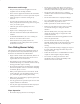
• lack of awareness of the effect of ground conditions, especially slopes; – use slow speeds on slopes and during tight turns; – stay alert for humps and hollows and other hidden hazards; • incorrect hitching and load distribution. • Use care when pulling loads or using heavy equipment. Preparation – Use only approved drawbar hitch points. • While mowing, always wear substantial footwear and long trousers. Do not operate the equipment when barefoot or wearing open sandals.
• Do not mow near drop–offs, ditches, steep banks or water. Wheels dropping over edges can cause rollovers, which may result in serious injury, death or drowning. Maintenance and Storage • Keep all nuts, bolts and screws tight to be sure the equipment is in safe working condition. • Never store the equipment with fuel in the tank inside a building where fumes can reach an open flame or spark. • Do not mow slopes when grass is wet.
Sound Pressure for Model 74402 This unit has a maximum sound pressure level at the operator’s ear of 86 dBA, based on measurements of identical machines per Directive 98/37/EC. Sound Power for Model 74402 This unit has a guaranteed sound power level of 100 dBA, based on measurements of identical machines per Directive 2000/14/EC. Vibration for Model 74402 This unit does not exceed a hand/arm vibration level of 3.22 m/s2, based on measurements of identical machines per Directive 98/37/EC.
Slope Chart 7
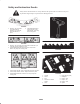
Safety and Instruction Decals Safety decals and instructions are easily visible to the operator and are located near any area of potential danger. Replace any decal that is damaged or lost. 93-6677 1. Warning—do not operate the mower with the deflector up or removed; keep the deflector in place. 2. Cutting/dismemberment hazard of hand or foot, mower blade—stay away from moving parts. 105-7015 93-7009 1. Warning—do not operate the mower with the deflector up or removed; keep the deflector in place. 2.
6-8717 1. Read the instructions before servicing or performing maintenance. 2. Check tire pressure every 25 operating hours. 106-8742 1. Parking brake 3. Grease every 25 operating hours. 4. Engine 106-8743 1. Height of cut Battery Symbols Some or all of these symbols are on your battery. 1. Explosion hazard 2. No fire, open flames, or smoking. 3. Caustic liquid/chemical burn hazard 4. Wear eye protection 5. Read the Operator’s Manual. 6. Keep bystanders a safe distance from the battery. 106-7043 1.
Gasoline and Oil Recommended Gasoline Warning Use UNLEADED Regular Gasoline suitable for automotive use (87 pump octane minimum). Leaded regular gasoline may be used if unleaded regular is not available. Gasoline is harmful or fatal if swallowed. Long–term exposure to vapors can cause serious injury and illness. Important Never use methanol, gasoline containing methanol, or gasohol containing more than 10% ethanol because the fuel system could be damaged. Do not mix oil with gasoline.
Controls Operation Become familiar with all of the controls (Fig. 3 and 4) before you start the engine and operate the machine. Note: Determine the left and right sides of the machine from the normal operating position. 3 2 Think Safety First Please carefully read all of the safety instructions and decals in the safety section. Knowing this information could help you, your family, pets or bystanders avoid injury. 1 Danger Mowing on wet grass or steep slopes can cause sliding and loss of control.
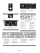
Starting and Stopping the Engine 2 1 3 Starting the Engine 4 1. Sit down on the seat and move the motion controls to the brake position. m–4268 Figure 7 2. Move the PTO (power take off) to Off (Fig. 5). 1. Off 2. Run 3. Start 4. Ignition 2 1 Stopping the Engine 1. Move the throttle lever to Fast (Fig. 6). m–4201 2. Move the PTO to Off (Fig. 5). Figure 5 1. PTO—On 3. Turn the ignition key to Off (Fig. 7). 2. PTO—Off 4.
2 3. While sitting on the seat, move the PTO to Off, and lock the motion control levers in neutral. Start the engine. While the engine is running, move the motion control levers to the center, unlocked position, engage the PTO, and rise slightly from the seat; the engine should stop. 1 m–4201 Figure 8 1. PTO—On Driving Forward or Backward 2. PTO—Off The throttle control regulates the engine speed as measured in rpm (revolutions per minute).
To go straight, apply equal pressure to both motion control levers (Fig. 9). To turn, release pressure on the motion control lever toward the direction you want to turn (Fig. 9). The farther you move the traction control levers in either direction, the faster the machine will move in that direction. To stop, pull the motion control levers to neutral. G F Backward 1. Move the levers to the center, unlocked position. 2. To go backward, slowly pull the motion control levers rearward (Fig. 9).
Positioning the Seat The seat can move forward and backward. Position the seat where you have the best control of the machine and are most comfortable. 1 1. Raise the seat and loosen the adjustment knobs (Fig. 12). 2 3 2. Move the seat to the desired position and tighten the knobs. m–6417 1 Figure 13 1. Control lever 2. Bolt 3. Control arm shaft Pushing the Machine by Hand Important Always push the machine by hand. Never tow the machine because damage may occur. m–6433 Figure 12 1.
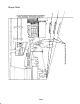
Removing and Installing the Engine Hood 1. To remove the hood, loosen the knobs and then pull the hood back and up (Fig. 16). 1 2 1 m–7276 Figure 14 1. Lever position for pushing the machine 2 2. Lever position for operating the machine m–6480 Figure 16 1. Engine hood 2. Knob To Operate the Machine 2. To install the hood, put the hooks into the slots and slide forward (Fig. 17). Move each bypass levers to the inside and pull them rearward, completely through the slot (Fig. 14). 3.
Side Discharge or Mulch Grass 1 This mower is able to mulch or side discharge grass. Coming from the factory, the mower is in mulching mode. 2 6 6 Danger Without the grass deflector, discharge cover, or complete grass catcher assembly mounted in place, you and others are exposed to blade contact and thrown debris. Contact with rotating mower blade(s) and thrown debris will cause injury or death.
Tips for Mowing Grass Long Grass Fast Throttle Setting If the grass is ever allowed to grow slightly longer than normal, or if it contains a high degree of moisture, raise the cutting height higher than usual and cut the grass at this setting. Then cut the grass again using the lower, normal setting. For best mowing and maximum air circulation, operate the engine at the Fast position.
Maintenance Note: Determine the left and right sides of the machine from the normal operating position. Recommended Maintenance Schedule Maintenance Service Interval Each use After first 5 hours Maintenance Procedure • Check the engine oil level. • Check the safety system. • Clean the mower housing. • Change the engine oil. Every 5 hours • Check the cutting blades. Every 25 hours • • • • • • Every 50 hours • Change the engine oil.2 Every 100 hours • • • • • Clean the cooling system.
Servicing the Engine Oil 1 2 Check the oil level daily or after every 8 hours. Change the oil after the first 5 operating hours and every 50 operating hours thereafter. Oil Type: Detergent oil (API service SF, SG, SH, SJ, or higher) Crankcase Capacity: 3 • 48 oz./1-1/2 qt. (1400 cc/1.4 l) when the filter is not changed; • 56 oz./1-3/4 qt. (1700 cc/1.7 l) when the filter is changed (Models 74403) m–6439 Figure 19 1. Oil dipstick 2. Filler tube Viscosity: See the table below. 3.
3. Disengage the PTO and set the parking brake. 2. Remove the old filter and wipe the filter adapter gasket surface (Fig. 22). 4. Stop the engine, remove the key, and wait for all moving parts to stop before leaving the operating position. 3. Apply a thin coat of clean oil to the rubber gasket on the replacement filter (Fig. 22). 5. Slide the drain hose over the drain valve. 3 6. Place a pan below the drain hose. Rotate oil drain valve to allow oil to drain (Fig. 21). 2 7.
Important worn. 2 1 Replace the foam element if it is torn or Cleaning the Paper Element: 1. Lightly tap the element on a flat surface to remove dust and dirt. 2. Carefully clean the rubber seal on the paper element to prevent debris from entering the engine. 3. Inspect the element for tears, an oily film, and damage to the rubber seal. Important Never clean the paper element with pressurized air or liquids, such as solvent, gas, or kerosene.
1 Servicing the Cutting Blades Maintain sharp blades throughout the cutting season because sharp blades cut cleanly without tearing or shredding the grass blades. Tearing and shredding turns grass brown at the edges, which slows growth and increases the chance of disease. Check the cutter blades daily for sharpness, and for any wear or damage. File down any nicks and sharpen the blades as necessary. If a blade is damaged or worn, replace it immediately with a genuine Toro replacement blade.
Checking for Bent Blades 1. Rotate the blades until the ends face forward and backward (Fig. 28). Measure from a level surface to the cutting edge, position A, of the blades (Fig. 28). Note this dimension. 2 m–6427 1 5 A 3 A 4 m–6430 Figure 29 1. Sail area of blade 2. Blade 3. Curved washer Sharpening the Blades 3 3 4. Blade bolt 5. Blade stiffener 1. Use a file to sharpen the cutting edge at both ends of the blade (Fig. 30). Maintain the original angle.
2. Install the blade stiffener, the curved washer (cupped side toward the blade) and the blade bolt (Fig. 29). Torque the blade bolt to 35–65 ft-lb (47–88 N⋅m). Greasing and Lubrication Lubricate the machine when shown on the Check Service Reference Aid decal (Fig. 32) located beneath the seat. Grease more frequently when operating conditions are extremely dusty or sandy. 1 Grease with No. 2 general purpose lithium base or molybdenum base grease. How to Grease m–6435 1.
4. Disconnect the negative (black) ground cable from the battery post (Fig. 34). 6. Secure the battery with the hold-down (Fig. 34). Checking the Electrolyte Level Warning Danger Incorrect battery cable routing could damage the tractor and cables causing sparks. Sparks can cause the battery gasses to explode, resulting in personal injury. Battery electrolyte contains sulfuric acid which is a deadly poison and causes severe burns.
Draining the Fuel Tank Important Do not overfill the battery because electrolyte (sulfuric acid) can cause severe corrosion and damage to the chassis. Danger 5. Wait five to ten minutes after filling the battery cells. Add distilled water, if necessary, until the electrolyte level is up to the Upper line (Fig. 35) on the battery case. In certain conditions, gasoline is extremely flammable and highly explosive. A fire or explosion from gasoline can burn you and others and can damage property. 6.
Replacing the Fuel Filter Leveling the Mower from Side-to-Side Replace the fuel filter after every 100 operating hours or yearly, whichever occurs first. The mower blades must be level from side to side. Check the side-to-side level any time you install the mower or when you see an uneven cut on your lawn. Never install a dirty filter if it is removed from the fuel line. 1. Park the machine on a level surface and disengage the blade control (PTO). 1.
Adjusting the Front-to-Rear Blade Slope 7. To level the blade(s), reposition the leveling bracket(s) in a different hole and install the washer and hairpin cotter. (Fig. 40 and 41). A front hole lowers the blade height and a rear hole raises its height. Adjust both sides as required. 1 Check the front-to-rear blade level any time you install the mower. If the front of the mower is more than 5/16 inch (7.9 mm) lower than the rear of the mower, adjust the blade level using the following instructions: 1.
8. Set the height-of-cut at position D [3 inch (76 mm)] and carefully rotate the blades so they are facing front to rear (Fig. 43). 9. Measure from the tip of the front blade to the flat surface and the tip of the rear blade to the flat surface (Fig. 43). If the front blade tip is not 1/16–5/16 inch (1.6–7.9 mm) lower than the rear blade tip, adjust the front locknuts. 1 1 2 2 m–6427 3 2 3 1 4 1 m–4634 Figure 44 2 1. Locknut and adjusting nut 2. Front tire 3 3 13.
Removing the Mower Warning Note: Before removing the mower, make a note for which holes are used in the leveling brackets (Fig. 47). The spring is under tension when installed and can cause personal injury. 1. Park the machine on a level surface and disengage the blade control (PTO). Be careful when removing the spring. 2. Move the motion control levers to the brake position, stop the engine, remove the key, and wait for all moving parts to stop before leaving the operating position. 6.
7. Slide the mower rearward to remove the mower belt from the engine pulley. 8. Slide the mower out from underneath the tractor. 3 Note: Retain all parts for future installation. Installing the Mower 1. Park the machine on a level surface and disengage the blade control (PTO). 2 2. Move the motion control levers to the brake position, stop the engine, remove the key, and wait for all moving parts to stop before leaving the operating position. 1 m–6420 Figure 48 3. Slide the mower under the tractor.
5. Sit on the seat and start the engine. Engage the PTO and let the mower run for one to three minutes. 6. Place the spring on the rod, with end wires down, and between the grass deflector brackets. Slide rod through second grass deflector bracket and internal lock washer (Fig. 50). 6. Disengage the PTO, stop the engine, and remove the ignition key. Wait for all moving parts to stop. 7. Insert rod at front of grass deflector into short stand-off on deck.
BK BN BLUE GREEN GREY ORANGE BU GN GY OR PTO CLUTCH BROWN BN BK Y W GY BN BLACK Y W VIO T R PK SW2 (PTO) 4 Y GN W SHOWN WITH PARK BRAKE DISENGAGED SW5 (BRAKE) SHOWN WITH PARK BRAKE DISENGAGED SW3 (BRAKE) PK YELLOW WHITE VIOLET TAN RED PINK SHOWN IN OFF POSITION 7 GND 1 WIRE COLOR CODES 5 2 4 3 35 1 I OR OR X K1 (KILL RELAY) W Y SW4 (SEAT) SHOWN WITH OPERATOR IN SEAT PK Y BU BU S SW1 (IGNITION) VIO R SOLENOID A F1 B BK Y F2 GND 10A F3 25A X I
Cleaning and Storage A. Run the engine to distribute the conditioned fuel through the fuel system (5 minutes). 1. Disengage the PTO, set the parking brake, stop the engine, and remove the key. B. Stop the engine, allow it to cool, and drain the fuel tank; refer to Draining the Fuel Tank, page 28. 2. Remove grass clippings, dirt, and grime from the external parts of the entire machine, especially the engine. Clean dirt and chaff from the outside of the engine cylinder head fins and blower housing. C.
Problem The starter does not crank. The engine g will not start, starts h d or ffails hard, il tto kkeep running. i The engine g loses power. Possible Causes Corrective Action 1. The blade control (PTO) is engaged. 1. Move the PTO to Disengaged. 2. The motion control levers are not in the brake position. 2. Move the motion control levers to the brake position. 3. The operator is not seated. 3. Sit on the seat. 4. The battery is dead. 4. Charge the battery. 5.
Problem The machine does not drive. There is abnormal vibration. Uneven cutting g height. g The blades do not rotate. Possible Causes Corrective Action 1. The traction belts are worn, loose, or broken. 1. Contact an Authorized Service Dealer. 2. The traction belts are off of the pulleys. 2. Contact an Authorized Service Dealer. 1. The engine mounting bolts are loose. 1. Tighten the engine mounting bolts. 2. The engine pulley, idler pulley, or blade pulley is loose. 2.