Form No. 3392-268 Rev C DH 210 Lawn Tractor Model No. 74585—Serial No. 315000001 and Up Register at www.Toro.com.
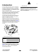
g000502 Figure 2 Introduction 1. Safety alert symbol This rotary-blade, riding lawn mower is intended to be used by residential homeowners. It is designed primarily for cutting grass on well-maintained lawns on residential properties. It is not designed for cutting brush or for agricultural uses. This manual uses 2 words to highlight information. Important calls attention to special mechanical information and Note emphasizes general information worthy of special attention.
Contents Mower Deck Maintenance.................................... 32 Servicing the Blades ......................................... 32 Removing the Mower........................................ 33 Installing the Mower.......................................... 34 Storage ................................................................... 34 Troubleshooting ...................................................... 36 Schematics ............................................................. 38 Safety .........
Fuel Safety Safety WARNING-Fuel is highly flammable. Take the following precautions. • Store fuel in containers specifically designed for this purpose. • Refuel outdoors only and do not smoke while refueling. • Add fuel before starting the engine. Never remove the cap of the fuel tank or add fuel while the engine is running or when the engine is hot.
• Before attempting to start the engine, disengage • • • • • • • • • • • • • all blade attachment clutches and shift into neutral. Do not operate without either the entire grass catcher or the deflector or a self-closing discharge-opening guard in place. Remember there is no such thing as a safe slope. Travel on grass slopes requires particular care.
straps should be directed down and outward from the machine. Toro Riding Mower Safety The following paragraph contains safety information specific to Toro products that is not included in the CEN standard. Use only Toro-approved attachments. The warranty may be voided if you use the machine with unapproved attachments. Sound Pressure This unit has a sound pressure level at the operator’s ear of 84 dBA, which includes an Uncertainty Value (K) of 1 dBA.
Slope Indicator g011841 Figure 3 This page may be copied for personal use. 1. The maximum slope you can safely operate the machine on is 10 degrees when mowing on side hills and 15 degrees when mowing uphill or downhill. Use the slope chart to determine the degree of slope of hills before operating. Do not operate this machine on a slope greater than 15 degrees. Fold along the appropriate line to match the recommended slope. 2. Align this edge with a vertical surface, a tree, building, fence pole, etc. 3.
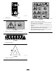
Safety and Instructional Decals Safety decals and instructions are easily visible to the operator and are located near any area of potential danger. Replace any decal that is damaged or missing. decal104-3237 104-3237 decaloemmarkt Manufacturer's Mark 1. Parking brake 1. Indicates the blade is identified as a part from the original machine manufacturer. decal93-7276 93-7276 1. Explosion hazard—wear eye protection. 2. Caustic liquid/chemical burn hazard—to perform first aid, flush with water. 3.
decal106-8552 106-8552 2. Recycle 1. Collect grass decal119-2725 119-2725 1. Warning—read the Operator's Manual. 2. Warning—remove the spark plug wire before performing any maintenance on the machine. 3. Tipping hazard—do not operate on slopes greater than 10 degrees. 4. Thrown object hazard; crushing hazard, bystanders—keep bystanders a safe distance from the machine. 5. Cutting hazard of hand or foot—stay away moving parts, keep all guards and shields in place. decal111-5941 111–5941 1.
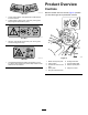
Product Overview Controls Become familiar with the controls (Figure 4) before you start the engine and operate the machine. decal119-2726 119-2726 1. Thrown object hazard—keep bystanders a safe distance from the machine. 2. Cutting hazard of hand or foot—stay away moving parts, keep all guards and shields in place. decal111-8217 111–8217 1. Warning—keep hands and feet away from moving parts; wait for moving parts to stop. g020501 decal119-2730 Figure 4 119-2730 1.
Specifications Operation Weight 246 kg Length 246 kg Width 110 cm Cutting width 102 cm Height 115 cm Engine speed 2,600 rpm Nominal engine power 10.17 Kw at 3,000 rpm Note: Determine the left and right sides of the machine from the normal operating position. Filling the Fuel Tank • For best results, use only clean, fresh (less than 30 days old), unleaded gasoline with an octane rating of 87 or higher ((R+M)/2 rating method).
2. Clean around the fuel tank cap and remove it. 3. Add unleaded regular gasoline to the fuel tank until the level is 1/4 to 1/2 inch (6 to 13 mm) below the bottom of the filler neck. Do not fill the fuel tank completely full. Using the Parking Brake Always set the parking brake whenever you stop the machine or leave it unattended. Setting the Parking Brake Important: Do not fill the fuel tank completely full. This space in the tank allows fuel to expand. 1.
Important: You must set the height-of-cut lever to the highest position (7) when you transport the machine off the lawn to prevent damaging the blades. 1. Push and hold in the button on the height-of-cut lever (Figure 7). g017870 Figure 7 g008253 Figure 6 1. Height-of-cut lever 1. Adjustment knobs 2. 2. Move the seat to the desired position and tighten the knobs. 3. Shift the height-of-cut lever to the desired position. Release the button. Starting the Engine Operating the Headlights 1.
4. Set the parking brake; refer to Setting the Parking Brake Setting the Parking Brake (page 12). 5. Disengage the blades (PTO); refer to Figure 4. 8. Stopping the Engine Note: The engine will not start if the blades 1. (PTO) are engaged. 6. After the engine starts, slowly shift the throttle control lever to the Fast position (Figure 9). When starting a cold engine, push the throttle control lever fully forward to the choke position (Figure 9). 2.
The safety interlock system is designed to stop the mower if: DANGER You could back over a child or bystander while the mower blades or other attachment is engaged and cause serious injury or death. • You shift into Reverse with the blades (PTO) engaged. • You remove the bag or dump the grass. • Do not mow in reverse unless it is absolutely necessary. Setting the KeyChoice® Switch to Operate in Reverse • Do not insert the KeyChoice key unless it is absolutely necessary.
Testing the Safety Interlock Pushing the Machine Manually System Important: Always push the machine manually. CAUTION Never tow the machine because it may damage the transaxle. If the safety interlock switches are disconnected or damaged, the machine could operate unexpectedly, causing personal injury. • Do not tamper with the interlock switches. • Check the operation of the interlock switches daily and replace any damaged switches before operating the machine.
Driving the Machine Forward or Backward Important: To prevent damage to the mower, always set the mower to the highest cutting position when you drive the machine off the lawn. The throttle control regulates the engine speed as measured in RPM (revolutions per minute). Place the throttle control in the Fast position for best performance. Stopping the Machine To go forward: 1. Release the parking brake; refer to Releasing the Parking Brake (page 12). 2.
Rear-Discharging the Grass Clippings Occasionally, you may need to cut the lawn without the grass collector when the grass is too long for collecting. 1. Disengage the locking latch (Figure 17). g017876 Figure 15 2. Disengage the blades (PTO) and move the throttle to the Slow position. 3. Pull the grass collector dump lever forward and tilt the grass collector (Figure 16). g017876 Figure 17 1. Locking latch 2. Disengage the blades (PTO) and move the throttle to the Slow position. 3.
g017883 g017878 Figure 19 Figure 20 1. Locking latch 4. Mow the grass with the grass collector in the open position as desired. 5. Before returning the grass collector to the operating position, move the machine forward to clear the grass collector of the deposited grass. 6. Slowly lower the dump lever to return the grass collector to the operating position. 1.
Operating Tips • For the best performance, operate the engine at the maximum speed. The mower requires air to thoroughly cut grass clippings, so do not set the height-of-cut too low or completely surround the mower in uncut grass. Always leave one side of the mower free from uncut grass to allow the air to be drawn into the mower. • Cut the grass slightly longer than normal to ensure that the cutting height of the mower does not scalp any uneven ground.
Maintenance Note: Determine the left and right sides of the machine from the normal operating position. Recommended Maintenance Schedule(s) Maintenance Service Interval Maintenance Procedure After the first 5 hours • Change the engine oil. Before each use or daily • • • • • • Check the safety interlock system. Check the engine oil level. Check the battery electrolyte level. Check the brake. Check the blades. Clean the mower housing. Every 25 hours • Grease and lubricate the machine.
Lubrication Greasing and Lubricating the Machine 6. Connect a grease gun to each fitting and pump grease into it. 7. Wipe up any excess grease. Where to Add Grease Service Interval: Every 25 hours/Yearly (whichever comes first)—Grease and lubricate the machine. (Grease and lubricate it more frequently when operating it in dusty or sandy conditions.) How to Grease the Machine Note: Grease the machine with a general-purpose grease. 1. Disengage the blades (PTO). 2. Set the parking brake. 3.
Engine Maintenance Servicing the Air Cleaner Service Interval: Every 25 hours—Service the air cleaner foam element. (Service it more frequently when operating the machine in dusty or dirty conditions.) Every 100 hours—Service the air cleaner paper element. (Service it more frequently when operating the machine in dusty or dirty conditions.) 1. Park the machine on a level surface. 2. Disengage the blades (PTO). 3. Set the parking brake. 4. Stop the engine and wait for all moving parts to stop. 5.
Note: Ensure that the rubber seal is flat against the air cleaner base. 2. Align the tabs on the air cleaner cover with the slots of the blower housing (Figure 23). 3. Hook the handle onto the cover and press down on the handle to lock the cover in place. Servicing the Engine Oil Oil Type: Detergent oil (API classification SJ or higher) g008268 Figure 25 Crankcase capacity: 1.4 L (47 oz) with filter; 1.3 L (44 oz) without filter 1. Dipstick 3. Filler tube 2. Metal end 4.
11. Clean around the dipstick and unscrew the cap (Figure 25). Servicing the Spark Plug 12. Slowly pour approximately 80% of the engine oil into the filler tube (Figure 25). Service Interval: Every 25 hours—Check the spark plug. 13. Check the engine oil level; refer to steps 9 and 10 of Checking the Engine Oil Level. Every 100 hours—Replace the spark plug. Use a Champion RC12YC or equivalent spark plug. Ensure that the air gap between the center and side electrodes is 0.030 inch (0.
Checking the Spark Plug 1. Fuel System Maintenance Look at the center of the spark plug (Figure 28). If you see light brown or gray on the insulator, the engine is operating properly. A black coating on the insulator usually means that the air cleaner is dirty. Draining the Fuel Tank Drain the fuel tank when you will not be using the machine for more than 30 days. DANGER In certain conditions, fuel and fuel vapors are extremely flammable and highly explosive.
9. Electrical System Maintenance Open the fuel shut-off valve and allow the fuel to drain into an approved fuel container or a drain pan. Note: Now is the best time to install a new fuel filter because the fuel tank is empty. 10. Install the fuel line onto the fuel filter. 11. Slide the hose clamp close to the fuel filter to secure the fuel line (Figure 29). Replacing the Headlight Bulbs 1. 2. 3. Replacing the Fuel Filter Service Interval: Every 100 hours/Yearly (whichever comes first) 4. 5. 6.
10. Bend the wire tabs in behind the bulb to hold it in place. 11. Install the bulb socket. Removing the Battery WARNING Battery terminals or metal tools could short against metal machine components causing sparks. Sparks can cause the battery gasses to explode, resulting in personal injury. Replacing the Fuses The electrical system is protected by fuses. They are located beneath the hood, near the fuel tank (Figure 33). If a fuse goes out, check the circuit wiring for a short.
WARNING Routing the battery cables improperly could damage the machine and cables, causing sparks. Sparks can cause the battery gasses to explode, resulting in personal injury. • Always disconnect the negative (black) battery cable before disconnecting the positive (red) cable. g006918 Figure 35 1. Filler caps 3. Lower line 2. Upper line • Always connect the positive (red) battery cable before connecting the negative (black) cable.
Charging the Battery Drive System Maintenance WARNING Charging the battery produces gasses that can explode. Never smoke near the battery and keep sparks and flames away from the battery. Checking the Tire Pressure Service Interval: Every 25 hours/Yearly (whichever comes first) Important: Always keep the battery fully charged (1.260 specific gravity), especially below 32°F (0°C) to prevent battery damage. 1. Remove the battery from the chassis; refer to Removing the Battery (page 28). 2.
Servicing the Grass Collector Note: If the machine takes more than 1 m (3 ft) to stop at high speed in the highest gear, adjust the brake. Checking the Brake Removing the Grass Collector Service Interval: Before each use or daily 1. Park the machine on a level surface. 2. Disengage the blades (PTO). 3. Set the parking brake. 4. Stop the engine and wait for all moving parts to stop. 5. Remove the ignition key. 6. Pull the drive control out to the Push position (Figure 13). 7.
seated on the mower. The mower will not function unless the grass collector is properly attached. Mower Deck Maintenance Unlock the locking pin to allow for emptying the grass collector. Servicing the Blades Note: Ensure that the grass collector is properly 2. Service Interval: Before each use or daily Cleaning the Grass Collector and Tunnel 1. Disengage the blades (PTO). 2. Set the parking brake. 3. Stop the engine and wait for all moving parts to stop. 4. Remove the ignition key. 5.
Installing the Blades Important: If the shear pins are broken, the mower belt may be damaged. Inspect the belt; refer to Removing the Mower (page 33). 1. Install the blades, washers, and blade bolts (Figure 40). Important: Ensure that the right and left blades are installed in the proper positions with the bent edges of the blades pointing toward the top of the mower to ensure proper cutting. Removing the Blades 1. Remove the mower; refer to Removing the Mower (page 33). 2.
Storage 1. Disengage the blades (PTO). 2. Set the parking brake. 3. Stop the engine and wait for all moving parts to stop. 4. Remove the ignition key. 5. Remove the grass collector and clean it; refer to Removing the Grass Collector (page 31). 6. Remove grass clippings, dirt, and grime from the external parts of the entire machine, especially the engine. Clean the dirt and chaff from the outside of the engine cylinder head fins and blower housing. g017882 Figure 44 1. Front arm linkage 4.
F. Start and run the engine until it will not start again. G. Recycle the old fuel according to local codes. H. Close the fuel shut-off valve. Important: Do not store stabilizer/conditioned fuel over 90 days. 13. Remove and inspect the spark plug; refer to Servicing the Spark Plug (page 25). With the spark plug removed from the engine, pour 2 tablespoons of engine oil into the spark plug hole. Use the electric starter to crank the engine and distribute the oil inside the cylinder.
Troubleshooting Problem The starter does not crank. The engine overheats. The machine does not drive. The engine does not start, starts hard, or fails to keep running. Possible Cause 1. The blade control (PTO) knob is engaged. 1. Move the blade control (PTO) knob to the Disengaged position. 2. The parking brake is not on. 3. The battery is dead. 4. The electrical connections are corroded or loose. 5. A fuse is blown. 6. A relay or switch is damaged. 2. Set the parking brake. 3. Charge the battery. 4.
Problem There is abnormal vibration. The blades do not rotate. The cutting height is uneven. Possible Cause Corrective Action 1. The blades are bent or unbalanced. 1. Install a new blades. 2. The blade mounting screws are loose. 3. The engine mounting bolts are loose. 4. There is a loose engine pulley, idler pulley, or blade pulley. 5. The engine pulley is damaged. 6. The blade drive belt is damaged. 2. Tighten the blade mounting screws. 3. Tighten the engine mounting bolts. 4.
Schematics g028270 (Rev.
European Privacy Notice The Information Toro Collects Toro Warranty Company (Toro) respects your privacy. In order to process your warranty claim and contact you in the event of a product recall, we ask you to share certain personal information with us, either directly or through your local Toro company or dealer. The Toro warranty system is hosted on servers located within the United States where privacy law may not provide the same protection as applies in your country.
Residential Products The Toro Warranty and The Toro GTS Starting Guarantee Conditions and Products Covered Owner Responsibilities The Toro Company and its affiliate, Toro Warranty Company, pursuant to an agreement between them, jointly promise to repair for the original purchaser1the Toro Product listed below if defective in materials or workmanship or if the Toro GTS (Guaranteed to Start) engine will not start on the first or second pull, provided the routine maintenance required in the Operator's Manua