
Use and Care Manual
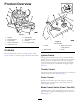


ProductOverview
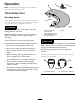
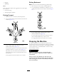
g028161
Figure4
1.Deector6.Operatorseat
2.Reardrivewheel
7.SmartSpeed™lever
3.Controlpanel
8.Footrest
4.Motioncontrollevers9.Frontcasterwheel
5.Heightofcutlever
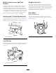
Controls
BecomefamiliarwithallofthecontrolsinFigure4and
Figure5beforeyoustarttheengineandoperatethemachine.
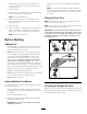
Figure5
ControlPanel
1.Throttle3.Bladecontrolswitch
(powertake-off)
2.Ignitionswitch
4.Choke
IgnitionSwitch
Theignitionswitchhasthreepositions,Off,RunandStart.
ThekeywillturntoStartandmovebacktoRunuponrelease.
TurningthekeytotheOffpositionwillstoptheengine;
however,alwaysremovethekeywhenleavingthemachine
topreventsomeonefromaccidentallystartingtheengine
(Figure5).
ThrottleControl
Thethrottlecontrolstheenginespeedandithasacontinuous
variablesettingfromSlowtoFast(Figure5).
ChokeControl
PullupontheChokecontroluntilitstopstochokethe
engine(Figure5).PushdownontheChokecontrolfor
normalengineoperation
BladeControlSwitch(PowerTake-Off)
Thebladecontrolswitch,representedbyapowertake-off
(PTO)symbol,engagesanddisengagespowertothemower
blades(Figure5).
13