
Use and Care Manual


G014973
1
2
3
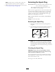
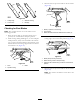
Figure48
1.Oppositebladeedge(inpositionformeasuring)
2.Levelsurface
3.Secondmeasureddistancebetweenbladeandsurface(B)
A.IfthedifferencebetweenAandBisgreaterthan
3mm(1/8inch),replacethebladewithanew
blade;refertoRemovingtheBlades(page38)and
InstallingtheBlades(page38).
Note:Ifabentbladeisreplacedwithanewone,
andthedimensionobtainedcontinuestoexceed
3mm(1/8inch),thebladespindlecouldbebent.
ContactanAuthorizedToroDealerforservice.
B.Ifthevarianceiswithinconstraints,movetothe
nextblade.
Repeatthisprocedureoneachblade.
RemovingtheBlades
Thebladesmustbereplacedifasolidobjectishit,ifthe
bladeisoutofbalance,orifthebladeisbent.Toensure
optimumperformanceandcontinuedsafetyconformance
ofthemachine,usegenuineTororeplacementblades.
Replacementbladesmadebyothermanufacturersmayresult
innon-conformancewithsafetystandards.
1.Holdthebladeendusingaragorthickly-paddedglove.
2.Removethebladebolt,thecurvedwasher,andthe
bladefromthespindleshaft(Figure49).
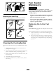
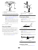
G027833
Figure49
1.Sailareaoftheblade3.Curvedwasher
2.Blade4.Bladebolt
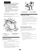
SharpeningtheBlades
1.Usealetosharpenthecuttingedgeatbothendsof
theblade(Figure50).
Note:Maintaintheoriginalangle.
Note:Thebladeretainsitsbalanceifthesameamount
ofmaterialisremovedfrombothcuttingedges.
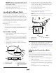
Figure50
1.Sharpenatoriginalangle
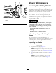
2.Checkthebalanceofthebladebyputtingitonablade
balancer(Figure51).
Note:Ifthebladestaysinahorizontalposition,the
bladeisbalanced,andcanbeused.
Note:Ifthebladeisnotbalanced,lesomemetaloff
theendofthesailareaonly(Figure50).
Figure51
1.Blade2.Balancer
3.Repeatthisprocedureuntilthebladeisbalanced.
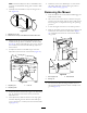
InstallingtheBlades
1.Installthebladeontothespindleshaft(Figure49).
38