
Operator's Manual


ProductOverview
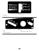
g020240
1
2
3
4
5
6
7
8
10
11
12
13
9
3
Figure5
1.Footrest
5.Controlpanel9.Deector
13.Frontcasterwheels
2.Height-of-cutlever6.Operatorseat
10.Engine
3.Motion-controllever7.Reardrivewheel
11.Washouttting
4.Smart-speedlever
8.Fuel-tankcap12.Mowerdeck
Controls
BecomefamiliarwithallcontrolsinFigure5andFigure6
beforeyoustarttheengineandoperatethemachine.
g027890
Figure6
ControlPanel
1.Throttle/Choke
3.Blade-controlswitch
(powertakeoff)
2.Ignitionswitch
IgnitionSwitch
Usethisswitchtostartthemowerengine.Ithas3positions:
START,RUN,andOFF.
Throttle/ChokeControl
Thethrottleandchokecontrolsarecombinedinto1control
lever.Thethrottlecontrolstheenginespeedandhasa
continuous-variablesettingfromSLOWtoFAST.Engagethe
chokebymovingtheleverpasttheFASTsettinguntilitstops
(Figure6).
Blade-ControlSwitch(PowerTakeoff)
Theblade-controlswitch,representedbyapower-takeoff
(PTO)symbol,engagesanddisengagespowertothemower
blades(Figure6).
Motion-ControlLevers
Usethemotion-controlleverstodrivethemachineforward,
reverse,andturneitherdirection.
ParkPosition
Movethemotion-controlleversoutwardfromthecenterto
thePARKpositionwhenexitingthemachine(Figure18).
Alwayspositionthemotion-controlleversintothePARK
positionwhenyoustopthemachineorleaveitunattended.
10