Form No. 3393-111 Rev C TimeCutter® SS 5000 Riding Mower Model No. 74731—Serial No. 315000001 and Up Register at www.Toro.com.
Introduction WARNING CALIFORNIA Proposition 65 Warning This product contains a chemical or chemicals known to the State of California to cause cancer, birth defects, or reproductive harm. The engine exhaust from this product contains chemicals known to the State of California to cause cancer, birth defects, or other reproductive harm. This machine is a ride-on, rotary-blade lawnmower intended to be used by homeowners in residential applications.
Charging the Battery......................................... 36 Servicing the Fuses .......................................... 38 Drive System Maintenance .................................. 38 Checking the Tire Pressure............................... 38 Releasing the Electric Brake ............................. 39 Mower Maintenance............................................. 39 Servicing the Cutting Blades ............................. 39 Leveling the Mower Deck..................................
Safety • Be alert, slow down and use caution when making turns. Look behind and to the side before changing directions. To reduce the potential for injury, comply with these safety instructions and always pay attention to the safety alert symbol, which means CAUTION, WARNING, or DANGER-"personal safety instruction." Failure to comply with the instruction may result in personal injury or death. • Never leave a running machine unattended.
Towing Safety • Do not make sudden turns or rapid speed changes. • Remove or mark obstacles such as rocks, tree • Do not attach towed equipment except at the hitch limbs, etc. from the mowing area. Tall grass can hide obstacles. point. • Follow the attachment manufacturer's • Avoid sudden starts when mowing uphill because recommendation for weight limits for towed equipment and towing on slopes. Towed weight must not exceed the weight of the machine, operator, and ballast.
• If fuel is spilled on clothing, change clothing • mower and any moving parts while engine is running. immediately. Never overfill the fuel tank. Replace gas cap and tighten securely. • Do not touch equipment or attachment parts which may be hot from operation. Allow to cool before attempting to maintain, adjust or service. General Service • Battery acid is poisonous and can cause burns. • Never operate a machine inside a closed area.
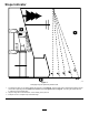
Slope Indicator g011841 Figure 3 This page may be copied for personal use. 1. The maximum slope you can safely operate the machine on is 15 degrees. Use the slope chart to determine the degree of slope of hills before operating. Do not operate this machine on a slope greater than 15 degrees. Fold along the appropriate line to match the recommended slope. 2. Align this edge with a vertical surface, a tree, building, fence pole, etc. 3. Example of how to compare slope with folded edge.
Safety and Instructional Decals Safety decals and instructions are easily visible to the operator and are located near any area of potential danger. Replace any decal that is damaged or lost. decal93-7009 93-7009 1. Warning—don't operate the mower with the deflector up or removed; keep the deflector in place. 2. Cutting/dismemberment hazard of hand or foot, mower blade—stay away from moving parts. decal110-6691 110-6691 1. Thrown object hazard—keep bystanders a safe distance from the machine. 2.
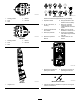
decal119-8814 decalbatterysymbols 119-8814 1. Parking position 4. Neutral 2. Fast 3. Slow 5. Reverse Battery Symbols Some or all of these symbols are on your battery 4. Neutral 2. Fast 3. Slow 5. Reverse 6. Keep bystanders a safe distance from the battery. 2. No fire, open flame, or smoking. 7. Wear eye protection; explosive gases can cause blindness and other injuries 3. Caustic liquid/chemical burn hazard 4. Wear eye protection 8. Battery acid can cause blindness or severe burns. 9.
decal131-1097 131-1097 1. Oil drain decal132-6863 132-6863 decal131-4036 131-4036 1. Maximum drawbar pull 36 kg (80 lb) 2. Read the Operator's Manual. decal131-3947 131–3947 1. Trim—slow 2. Tow—medium 3.
decal121-0773 121-0773 1. Fast 2. Continuous variable setting 4. Choke 5. Power take-off (PTO), Blade control switch 3.
decal132-0869 132-0869 1. Warning—read the Operator's Manual. 5. Ramp tipping 3. Cutting hazard of hand, hazard—when loading mower blade; pinching onto a trailer, do not use hazard of hand, belt—keep dual ramps; only use a hands and feet away from single ramp wide enough moving parts; keep all for the machine and that guards and shields in place. has an incline less than 15 degrees; back up the ramp (in reverse) and drive forward off the ramp. 2.
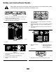
Product Overview g028411 Figure 4 1. Footrest 8. Gas tank cap 2. Deflector 9. Smart Speed™ lever 3. Height-of-cut lever 10. Rear drive wheel 4. Motion-control lever 5. Control panel 11. Mower deck 12. Anti-scalp roller 6. Operator seat 13. Front caster wheel 7.
Blade-Control Switch (Power Take-off) Controls Become familiar with all of the controls before you start the engine and operate the machine. The blade-control switch, represented by a power take-off (PTO) symbol, engages and disengages power to the mower blades (Figure 5). Motion-Control Levers and Park Position The motion-control levers are speed sensitive controls of independent wheel motors.
Fuel Window Operation The fuel window located on the left hand side of the machine can be used to verify the presence of gasoline in the tank (Figure 7). Note: Determine the left and right sides of the machine from the normal operating position. Adding Fuel • For best results, use only clean, fresh (less than • g014521 Figure 7 1. Fuel presence window • • Height-of-Cut Lever The height of cut lever allows the operator to lower and raise the deck from the seated position.
Important: Do not use fuel additives containing methanol or ethanol. DANGER In certain conditions during fueling, static electricity can be released causing a spark which can ignite the gasoline vapors. A fire or explosion from gasoline can burn you and others and can damage property. Add the correct amount of gas stabilizer/conditioner to the gas. Note: A fuel stabilizer/conditioner is most effective when mixed with fresh gasoline.
Breaking in a New Machine New engines take time to develop full power. Mower decks and drive systems have higher friction when new, placing additional load on the engine. Allow 40 to 50 hours of break-in time for new machines to develop full power and best performance. Think Safety First Operating Safety Please carefully read all of the safety instructions and decals in the safety section. Knowing this information could help you, your family, pets or bystanders avoid injury. g000513 Figure 9 1.
The safety-interlock system is designed to prevent the engine from starting unless: Starting the Engine • The blades are disengaged. Note: A warm or hot engine may not require choking. • The motion-control levers are in the PARK position. Important: Do not engage the starter for more than 5 seconds at a time. Engaging the starter motor for more than 5 seconds can damage the starter motor. If the engine fails to start, wait 10 seconds before operating the engine starter again.
Engaging the Blades Driving the Machine Important: Do not engage the blades when Driving the machine benefits from an understanding of what zero-turn-radius mower means. The drive wheels turn independently, powered by hydraulic motors on each axle; hence one side can turn in reverse while the other turns forward causing the machine to spin rather than turn. This vastly improves the machine maneuverability but may require some adjustment if the operator is unfamiliar. parked in tall grass.
Using the Smart SpeedTM Control System Tow This is the medium speed. The suggested uses for this speed are as follows: The Smart Speed TM Control-System lever, located below the operating position (Figure 15), gives the operator a choice to drive the machine at 3 ground speed ranges—trim, tow, and mow. • Bagging • Mulching Mow This is the fastest speed. The suggested uses for this speed are as follows: • Normal mowing • Transporting the machine Driving Forward g027625 Figure 15 1.
Driving Backward Adjusting the Height-of-Cut Note: Always use caution when backing up and Note: The TRANSPORT position is the highest height-of-cut position or cutting height (115 mm (4.5 inches)) as shown in Figure 18. turning. 1. Move the levers to the center, unlocked position. 2. To go backward, look behind you and down, as you slowly pull the motion-control levers rearward (Figure 17). Height-of-cut is controlled by the lever located to the right of the operating position (Figure 18).
Adjusting the Anti-Scalp Rollers Positioning the Seat Whenever you change the height-of-cut, it is recommended to adjust the height of the anti-scalp rollers. Note: Adjust the anti-scalp rollers so the rollers do not touch the ground in normal, flat mowing areas. 1. Disengage the blade-control switch (PTO), move the motion-control levers to the NEUTRAL-LOCK position and set the parking brake. 2.
Adjusting the Motion-Control Levers 3. Locate the bypass levers on the frame on both sides of the engine. Adjusting the Height 4. Move the bypass levers forward through the key hole and down to lock them in place as shown in Figure 22 . Ensure this is done for each lever. 5. Move the motion-control levers inward to the NEUTRAL position and turn the ignition key to the RUN position. Do not start the machine. parts to stop before leaving the operating position.
Grass Deflector Transporting the Machine The mower has a hinged grass deflector that disperses clippings to the side and down toward the turf. Use a heavy-duty trailer or truck to transport the machine. Ensure that the trailer or truck has all necessary brakes, lighting, and marking as required by law. Please carefully read all the safety instructions. Knowing this information could help you, your family, pets, or bystanders avoid injury.
Loading the Machine WARNING Loading a machine onto a trailer or truck increases the possibility of tip-over and could cause serious injury or death. Use extreme caution when loading or unloading machines onto a trailer or a truck. Use a full-width ramp that is wider than the machine for this procedure. Back up ramps and drive forward down ramps (Figure 24). • Use extreme caution when operating a machine on a ramp. • Use only a full-width ramp; do not use individual ramps for each side of the machine.
Operating Tips Fast Throttle Setting For best mowing and maximum air circulation, operate the engine at the FAST position. Air is required to thoroughly cut grass clippings, so do not set the height-of-cut so low as to totally surround the mower by uncut grass. Always try to have one side of the mower free from uncut grass, which allows air to be drawn into the mower.
Avoid Cutting Too Low If the cutting width of the mower is wider than the mower you previously used, raise the cutting height to ensure that uneven turf is not cut too short. Long Grass If the grass is ever allowed to grow slightly longer than normal, or if it contains a high degree of moisture, raise the cutting height higher than usual and cut the grass at this setting. Then cut the grass again using the lower, normal setting.
Maintenance Note: Determine the left and right sides of the machine from the normal operating position. Recommended Maintenance Schedule(s) Maintenance Service Interval Maintenance Procedure After the first 5 hours • Change the engine oil and filter. Before each use or daily • • • • • Check the safety-interlock system. Check the engine-oil level. Clean the air intake screen. Check the cutting blades. Inspect the grass deflector for damage. After each use • Clean the mower deck housing.
Pre-Maintenance Procedures Lubrication Raising the Seat Service Interval: Every 25 hours—Grease all lubrication points. Make sure the motion-control levers are locked in the PARK position. Lift the seat forward. Grease Type: No. 2 general-purpose, lithium-based grease Greasing the Bearings The following components can be accessed by raising the seat: 1. Park the machine on a level surface and disengage the blade-control switch. • Serial plate 2.
5. Engine Maintenance Wipe up any excess grease. Servicing the Air Cleaner Note: Service the air cleaner more frequently (every few hours) if operating conditions are extremely dusty or sandy. Removing the Elements 1. Park the machine on a level surface and disengage the blade-control switch (PTO). 2. Engage the parking brake, stop the engine, remove the key, and wait for all moving parts to stop before leaving the operating position. 3.
5. Servicing the Engine Oil Remove the foam element from the paper element (Figure 29). Oil Type: Detergent oil (API service SF, SG, SH, SJ, or SL) Crankcase Capacity: 2.4 L (2.5 US qt) Viscosity: See the table below. g027802 Figure 29 Servicing the Foam Element Service Interval: Every 25 hours/Monthly (whichever comes first)—Clean the air-cleaner foam element (more often in dusty, dirty conditions).
g029368 Figure 31 Changing the Engine Oil and Oil Filter Service Interval: After the first 5 hours/After the first month (whichever comes first)—Change the engine oil and filter. Every 100 hours/Yearly (whichever comes first)—Change the engine oil (more often in dusty, dirty conditions). Every 100 hours/Yearly (whichever comes first)—Change the oil filter (more often in dusty, dirty conditions). Note: Change the engine-oil filter more frequently when operating conditions are extremely dusty or sandy.
5. Change the engine oil filter (Figure 33). g027799 g027477 Figure 33 Note: Ensure that the oil-filter gasket touches the engine, and then turn the filter an extra 3/4 turn.
6. Removing the Spark Plug Slowly pour approximately 80% of the specified oil into the filler tube and slowly add the additional oil to bring it to the Full mark (Figure 34). 1. Disengage the PTO and ensure the parking brake is engaged. 2. Stop the engine, remove the key, and wait for all moving parts to stop before leaving the operating position.
Installing the Spark Plug Fuel System Maintenance Tighten the spark plug(s) to 25–30 N-m (18.5–22.1 ft-lb). DANGER In certain conditions, gasoline is extremely flammable and highly explosive. A fire or explosion from gasoline can burn you and others and can damage property. • Perform any fuel related maintenance when the engine is cold. Do this outdoors in an open area. Wipe up any gasoline that spills.
Electrical System Maintenance WARNING CALIFORNIA Proposition 65 Warning Battery posts, terminals, and related accessories contain lead and lead compounds, chemicals known to the State of California to cause cancer and reproductive harm. Wash hands after handling. g027939 Charging the Battery Removing the Battery WARNING Battery terminals or metal tools could short against metal machine components causing sparks. Sparks can cause the battery gasses to explode, resulting in personal injury.
Charging the Battery WARNING Incorrect battery cable routing could damage the machine and cables causing sparks. Sparks can cause the battery gasses to explode, resulting in personal injury. Service Interval: Before storage—Charge the battery and disconnect battery cables. • Always disconnect the negative (black) battery cable before disconnecting the positive (red) cable. 1. Remove the battery from the chassis; refer to Removing the Battery. 2.
Servicing the Fuses Drive System Maintenance The electrical system is protected by fuses. It requires no maintenance; however, if a fuse blows, check the component/circuit for a malfunction or short. Checking the Tire Pressure Fuse: • Main F1-30 amp, blade-type Service Interval: Every 25 hours—Check tire pressure. • Charge Circuit F2-25 amp, blade-type 1. Remove the screws securing the control panel to the machine. Retain all fasteners 2.
Mower Maintenance Releasing the Electric Brake Servicing the Cutting Blades The electric brake releases by manually rotating the link arms forward. Once the electric brake is energized the brake will reset. Maintain sharp blades throughout the cutting season because sharp blades cut cleanly without tearing or shredding the grass blades. Tearing and shredding turns grass brown at the edges, which slows growth and increases the chance of disease. To release the brake: 1.
Inspecting the Blades 3. Service Interval: Before each use or daily—Check the cutting blades. 1. Inspect the cutting edges (Figure 44). If the edges are not sharp or have nicks, remove and sharpen the blades; refer to Sharpening the Blades (page 41). 2. Inspect the blades, especially the curved area (Figure 44). If you notice any damage, wear, or a slot forming in this area (item 3 or 4 in Figure 44), immediately install a new blade. Measure from the tip of the blade to the flat surface (Figure 46).
5. Removing the Blades Measure from the tip of the blade to the flat surface (Figure 48. The blades must be replaced if a solid object is hit, if the blade is out of balance, or the blade is bent. To ensure optimum performance and continued safety conformance of the machine, use genuine Toro replacement blades. Replacement blades made by other manufacturers may result in non-conformance with safety standards. Note: The variance should be no more than 3 mm (1/8 inch).
2. Check the balance of the blade by putting it on a blade balancer (Figure 51). If the blade stays in a horizontal position, the blade is balanced and can be used. If the blade is not balanced, file some metal off the end of the sail area only (Figure 50). Repeat this procedure until the blade is balanced. g000553 Figure 51 1. Blade g005278 Figure 52 2. Balancer 1. Blades side to side 3. Outside cutting edges 2. Sail area of blade 4.
9. Check the side-to-side adjustments again. Repeat this procedure until the measurements are correct. 10. Continue leveling the deck by checking the front-to-rear blade slope; refer to Adjusting the Front-to-Rear Blade Slope (page 43). Adjusting the Front-to-Rear Blade Slope Check the front-to-rear blade level any time you install the mower. If the front of the mower is more than 7.9 mm (5/16 inch) lower than the rear of the mower, adjust the blade level using the following instructions: 1. 2. 3.
Removing the Mower 1. Park the machine on a level surface and disengage the blade-control switch. 2. Move the motion-control levers outward to the PARK position, stop the engine, remove the key, and wait for all moving parts to stop before leaving the operating position. 3. Lower the height-of-cut lever to the lowest position. 4. Remove the hairpin cotter from the front support rod and remove the rod from the deck bracket (Figure 48). Carefully lower the front of the mower deck to the ground.
Mower Belt Maintenance Inspecting the Belts Service Interval: Every 25 hours—Check the belts for wear/cracks. Check the belts for cracks, frayed edges, burn marks, or any other damage. Replace damaged belts. Replacing the Mower Belt Squealing when the belt is rotating, blades slipping when cutting grass, frayed belt edges, burn marks, and cracks are signs of a worn mower belt. Replace the mower belt if any of these conditions are evident. 1.
Replacing the Grass Deflector Slide rod through second grass deflector bracket (Figure 59). 7. Service Interval: Before each use or daily—Inspect the grass deflector for damage. Important: The grass deflector must be spring loaded in the down position. Lift the deflector up to test that it snaps to the full down position. WARNING An uncovered discharge opening could allow the lawn mower to throw objects in the operator's or bystander's direction and result in serious injury.
Cleaning 6. Disengage the blade-control switch, stop the engine, and remove the ignition key. Wait for all moving parts to stop. Washing the Underside of the Mower 7. Turn the water off and remove the coupling from the washout fitting. Note: If the mower is not clean after one Service Interval: After each use—Clean the mower deck housing. washing, soak it and let it stand for 30 minutes. Then repeat the process. 8.
Storage cylinder. Install the spark plug(s). Do not install the wire on the spark plug(s). Cleaning and Storage 12. Clean any dirt and chaff from the top of the mower. 1. Disengage the blade-control switch, move the motion controls outward to the PARK position, stop the engine, and remove the key. 13. Scrape any heavy buildup of grass and dirt from the underside of the mower, then wash the mower with a garden hose. 2.
Troubleshooting Problem Possible Cause The fuel tank is showing signs of collapsing or the machine is showing signs of frequently running out of fuel. 1. The air cleaner paper element clogged. The engine overheats. 1. The engine load is excessive. 1. Reduce ground speed. 2. The oil level in the crankcase is low. 3. The cooling fins and air passages under the engine blower housing are plugged. 4. The air cleaner is dirty. 2. Add oil to the crankcase. 3.
Problem The machine does not drive. There is abnormal vibration. The cutting height is uneven. Possible Cause 1. The bypass valves are open. 1. Close the tow valves. 2. The traction belts are worn, loose, or broken. 3. The traction belts are off of the pulleys. 4. The transmission has failed. 2. Contact an Authorized Service Dealer. 1. The engine mounting bolts are loose. 1. Tighten the engine mounting bolts. 2. The engine pulley, idler pulley, or blade pulley is loose. 3.
Schematics g028022 Electrical Diagram (Rev.
The Toro Total Coverage Warranty TimeCutter and TITAN Mowers Limited Warranty (see warranty periods below) Conditions and Products Covered The Toro Company and its affiliate, Toro Warranty Company, pursuant to an agreement between them, jointly promise to the original purchaser to repair the Toro Products listed below if defective in materials or workmanship.