Form No. 3408-588 Rev B TimeCutter® SS 4225 or 5000 Riding Mower Model No. 74721—Serial No. 400000000 and Up Model No. 74732—Serial No. 400000000 and Up Register at www.Toro.com.
WARNING CALIFORNIA Proposition 65 Warning This product contains a chemical or chemicals known to the State of California to cause cancer, birth defects, or reproductive harm. The engine exhaust from this product contains chemicals known to the State of California to cause cancer, birth defects, or other reproductive harm. g188142 Figure 1 Under the seat This spark ignition system complies with Canadian ICES-002 1.
Contents Checking the Tire Pressure............................... 35 Releasing the Electric Brake ............................. 36 Mower Maintenance............................................. 36 Servicing the Cutting Blades ............................. 36 Leveling the Mower Deck.................................. 39 Removing the Mower Deck............................... 41 Installing the Mower.......................................... 42 Replacing the Grass Deflector ..........................
Safety This machine has been designed in accordance with ANSI B71.1-2012. General Safety This product is capable of amputating hands and feet and of throwing objects. Always follow all safety instructions to avoid serious personal injury. Using this product for purposes other than its intended use could prove dangerous to you and bystanders. • Read and understand the contents of this Operator’s Manual before you start the engine.
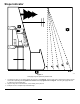
Slope Indicator g011841 Figure 3 This page may be copied for personal use. 1. The maximum slope you can safely operate the machine on is 15 degrees. Use the slope chart to determine the degree of slope of hills before operating. Do not operate this machine on a slope greater than 15 degrees. Fold along the appropriate line to match the recommended slope. 2. Align this edge with a vertical surface, a tree, building, fence pole, etc. 3.
Safety and Instructional Decals Safety decals and instructions are easily visible to the operator and are located near any area of potential danger. Replace any decal that is damaged or missing. decal93-7009 93-7009 1. Warning—do not operate the mower with the deflector up or removed; keep the deflector in place. 2. Cutting/dismemberment hazard of hand or foot, mower blade—stay away from moving parts. decal105-7015 105-7015 For models with 42-inch decks decal112-9840 112-9840 1.
decal119-8814 119-8814 1. Parking position 4. Neutral 2. Fast 3. Slow 5. Reverse decal119-8815 119-8815 1. Parking position 4. Neutral 2. Fast 3. Slow 5. Reverse decal119-8871 119-8871 For models with 42-inch decks 1. Height-of-cut decal121-2989b 121-2989 1. Bypass lever position for pushing the machine decal119-8870 119-8870 For models with 50-inch decks 1. Height-of-cut 7 2.
decalbatterysymbols Battery Symbols Some or all of these symbols are on your battery decal132-0872 132-0872 1. Thrown object hazard—keep bystanders away from the machine. 3. Severing hazard of hand or foot—keep away from moving parts. 1. Explosion hazard 6. Keep bystanders a safe distance away from the battery. 2. Thrown object hazard, raised baffle—do not operate the machine with an open deck; use a bagger or a baffle. 4.
decal131-4161 131-4161 For models with 42-inch decks 1. Fast 2. Slow 3. Power takeoff decal131-4162a 131-4162 For models with 50-inch decks 1. Fast 2. Continuous-variable setting 3. Slow 4.
decal132-0869 132-0869 1. Warning—read the Operator's Manual. 5. Ramp tipping 3. Cutting hazard of hand, hazard—when loading mower blade; pinching onto a trailer, do not use hazard of hand, belt—keep dual ramps; only use a hands and feet away from single ramp wide enough moving parts; keep all for the machine and that guards and shields in place. has an incline less than 15 degrees; back up the ramp (in reverse) and drive forward off the ramp. 2.
Product Overview g027933 Figure 4 1. Grass deflector 4. Height-of-cut lever 7. Footrest 10. Control panel 2. Rear drive wheel 5. Operator seat 8. Engine 11. Engine guard 3. Motion-control levers 6. Smart Speed™ lever 9. Fuel-tank cap 12. Front caster wheel Controls Ignition Switch Become familiar with all the controls in Figure 4 and Figure 5 before you start the engine and operate the machine. Use this switch to start the mower engine. It has 3 positions: START , RUN, and OFF.
Smart Speed™ Control System Lever Operation Note: Determine the left and right sides of the machine from the normal operating position. The Smart Speed™ Control-System lever, located below the operating position, gives you a choice to drive the machine at 3 speed ranges— trim, tow, and mow (Figure 21). Before Operation Fuel-Presence Window Before Operation Safety You can use the fuel window, located on the left side of the machine, to verify the presence of fuel in the tank (Figure 6).
Using Stabilizer/Conditioner containers on the ground, away from your vehicle before filling. • Remove the equipment from the truck or trailer and refuel it while it is on the ground. If this is not possible, then refuel from a portable container rather than a fuel-dispenser nozzle.
DANGER Operating the machine on wet grass or steep slopes can cause sliding and loss of control. • Do not operate on slopes greater than 15 degrees. • Reduce speed and use extreme caution on slopes. • Do not operate the machine near water. DANGER Wheels dropping over edges can cause rollovers, which may result in serious injury, death, or drowning. Do not operate the machine near drop-offs.
Testing the Safety-Interlock System CAUTION This machine produces sound levels in excess of 85 dBA at the operator’s ear and can cause hearing loss through extended periods of exposure. Test the safety-interlock system before you use the machine each time. If the safety system does not operate as described below, have an Authorized Service Dealer repair the safety system immediately. Wear hearing protection when operating this machine. 1.
Positioning the Seat Adjusting the Tilt The seat can move forward and backward. Position the seat where you have the best control of the machine and are most comfortable (Figure 10). You can adjust the motion-control levers forward or rearward for your comfort. 1. Loosen the upper bolt holding the control lever to the control-arm shaft. 2. Loosen the lower bolt just enough to pivot the control lever forward or rearward (Figure 11). 3.
• A rollover can occur before the tires lose traction. vibration in the machine. Make all necessary repairs before resuming operation. • Avoid operating the machine on wet grass. Tires • Slow down and use caution when making turns may lose traction; regardless if the brakes are available and functioning. and crossing roads and sidewalks with the machine. Always yield the right-of-way. • Avoid starting, stopping, or turning the machine • Disengage the drive to the cutting unit and shut on a slope.
Operating the Mower Operating the Throttle Blade-Control Switch (PTO) You can move the throttle control between the FAST and SLOW positions (Figure 15). The blade-control switch (PTO) starts and stops the mower blades and any powered attachments. Always use the FAST position when turning on the mower deck with the blade-control switch (PTO).
Starting the Engine CAUTION Children or bystanders may be injured if they move or attempt to operate the machine while it is unattended. Note: A warm or hot engine may not require choking. Important: Do not engage the starter for more than 5 seconds at a time. Engaging the starter motor for more than 5 seconds can damage the starter motor. If the engine fails to start, wait 10 seconds before operating the engine starter again.
Driving the Machine 2. To go backward, slowly pull the motion-control levers rearward (Figure 20). The drive wheels turn independently, powered by hydraulic motors on each axle. You can turn 1 side in reverse while you turn the other forward, causing the machine to spin rather than turn. This greatly improves the machine maneuverability but may require sometime for you to adapt to how it moves. The throttle control regulates the engine speed as measured in rpm (revolutions per minute).
Stopping the Machine The following are only recommendations for use. Adjustments vary by grass type, moisture content, and the height of the grass. Suggested uses: Trim Parking X Heavy, wet grass X Training X Tow To stop the machine, move the motion-control levers to NEUTRAL and outward to the PARK position, disengage the blade-control switch, ensure that the throttle is in the FAST position, and turn the ignition key to OFF. Remove the key from the ignition switch.
Adjusting the Anti-Scalp Rollers Operating Tips Using the Fast Throttle Setting For best mowing and maximum air circulation, operate the engine at the FAST position. Air is required to thoroughly cut grass clippings, so do not set the height-of-cut so low as to totally surround the mower in uncut grass. Always try to have 1 side of the mower free from uncut grass, which allows air to be drawn into the mower.
Pushing the Machine by Hand drop onto your lawn. To avoid this, move onto a previously cut area with the blades engaged or you can disengage the mower deck while moving forward. Important: Always push the machine by hand. Keeping the Underside of the Mower Clean Do not tow the machine, because damage to the hydraulic drive system may occur. This machine has an electric-brake mechanism. To push the machine, turn the ignition key to the RUN position.
Loading the Machine Note: If the machine fails to move, the electric brake may still be engaged. You can release the electric brake if necessary; refer to Releasing the Electric Brake (page 36). Use extreme caution when loading or unloading machines onto a trailer or a truck. Use a full-width ramp that is wider than the machine for this procedure. Back up the ramp and drive forward down the ramp (Figure 26).
g027996 Figure 27 1. Full-width ramp in stowed position 4. Ramp is at least 4 times as long as the height of the trailer or truck bed to the ground 2. Side view of full-width ramp in loading position 5. H=height of the trailer or truck bed to the ground 3. Not greater than 15 degrees 6.
Maintenance Note: Determine the left and right sides of the machine from the normal operating position. Recommended Maintenance Schedule(s) Maintenance Service Interval Before each use or daily Maintenance Procedure • • • • • Check the safety-interlock system. Check the air cleaner for dirty, loose or damaged parts. Check the engine-oil level. Inspect the blades. Inspect the grass deflector for damage. After each use • Clean the mower-deck housing. Every 25 hours • Grease all the lubrication points.
Pre-Maintenance Procedures Raising the Seat Maintenance and Storage You can access the following components by raising the seat: Make sure that the motion-control levers are locked in the PARK position. Lift the seat forward. • Before repairing the machine do the following: • • • • • • • • • • • • • • • • Serial plate – Disengage the drives. – Engage the parking brake. – Shut off the engine and remove the key. – Disconnect the spark-plug wire. Park the machine on a level surface.
Lubrication Engine Maintenance Greasing the Bearings Engine Safety Service Interval: Every 25 hours—Grease all the lubrication points. Shut off the engine before checking the oil or adding oil to the crankcase. Grease Type: No. 2 lithium grease Servicing the Air Cleaner 1. Park the machine on a level surface and disengage the blade-control switch. 2.
Checking the Engine-Oil Level Service Interval: Before each use or daily—Check the engine-oil level. 1. Park the machine on a level surface, disengage the blade-control switch, shut off the engine, and remove the key. 2. Make sure that the engine is stopped, level, and cool so the oil has time to drain into the sump. 3. Check the engine-oil level (Figure 32). g023919 Figure 30 1. Air-cleaner latch 3. Paper element 2. Engine 4.
Changing the Engine Oil and the Engine-Oil Filter Service Interval: Every 100 hours—Change the engine oil and the engine-oil filter. Note: The drain plug is attached to the drain hose. Note: Dispose the used oil at a recycling center. Fill with oil as specified in the table shown in Figure 31. 1. Park the machine so that the drain side is slightly lower than the opposite side to ensure that the oil drains completely. 2.
Servicing the Spark Plug Service Interval: Every 200 hours—Check the spark plug(s) condition and gap. Every 500 hours—Replace the spark plug(s). Type: Champion XC12YC or equivalent that is RFI compliant Air Gap: 0.76 mm (0.03 inch) Removing the Spark Plug 1. Disengage the blade-control switch, move the motion-control levers outward to the PARK position, shut off the engine, and remove the key. 2.
Fuel System Maintenance DANGER In certain conditions, fuel is extremely flammable and highly explosive. A fire or explosion from fuel can burn you, others, and can damage property. g027479 Figure 37 • Perform any fuel-related maintenance when the engine is cold. Do this outdoors in an open area. Wipe up any fuel that spills. Installing the Spark Plug Tighten the spark plug to 25 to 29 N·m (18 to 22 ft-lb).
Electrical System Maintenance Electrical System Safety • Disconnect the battery before repairing the machine. Disconnect the negative terminal first and the positive last. Connect the positive terminal first and the negative last. Charge the battery in an open, well-ventilated area, away from sparks and flames. Unplug the charger before connecting or disconnecting the battery. Wear protective clothing and use insulated tools.
Charging the Battery Note: Retain all fasteners. Service Interval: Before storage—Charge the battery and disconnect the battery cables. WARNING Incorrect battery-cable routing could damage the machine and cables causing sparks. Sparks can cause the battery gasses to explode, resulting in personal injury. 1. Remove the battery from the chassis; refer to Removing the Battery (page 33). 2. Charge the battery for a minimum of 1 hour at 6 to 10 A. Note: Do not overcharge the battery.
Servicing the Fuses Drive System Maintenance The electrical system is protected by fuses. It requires no maintenance; however, if a fuse blows, check the component/circuit for a malfunction or short. Checking the Tire Pressure Fuse type: • Main—F1 (30 A, blade-type) Service Interval: Every 25 hours—Check tire pressure. • Charge Circuit—F2 (25 A, blade-type) 1. Maintain the air pressure in the front and rear tires as specified. Uneven tire pressure can cause uneven cut.
Mower Maintenance Releasing the Electric Brake Servicing the Cutting Blades You can manually disengage the electric brake by rotating the link arms forward. Once the electric brake is energized, the brake engages again. 1. Turn the ignition key to the disconnect the battery. 2. Locate the shaft on the electric brake where the brake link arms are connected (Figure 44). 3. Rotate the shaft forward to release the brake. OFF To ensure a superior quality of cut, keep the blades sharp.
g006530 Figure 45 1. Cutting edge 3. Wear/slot forming 2. Curved area 4. Crack g014973 Figure 47 1. Blade (in position for measuring) Checking for Bent Blades 2. Level surface 3. Measured distance between blade and the surface (A) Note: The machine must be on a level surface for the following procedure. 4. 1. Raise the mower deck to the highest height-of-cut position. 2.
Removing the Blades Replace the blades if they hit a solid object, or if the blade is out of balance or bent. 1. Hold the blade end using a rag or thickly padded glove. 2. Remove the blade bolt, curved washer, and blade from the spindle shaft (Figure 50). g014973 Figure 49 1. Opposite blade edge (in position for measuring) 2. Level surface 3. Second measured distance between blade and surface (B) A.
g000553 Figure 52 1. Blade 3. 2. Balancer Repeat this procedure until the blade is balanced. Installing the Blades g009682 1. Install the blade onto the spindle shaft (Figure 50). Figure 53 Mower Decks with 2 Blades Important: The curved part of the blade must point upward toward the inside of the mower to ensure proper cutting. 2. Install the curved washer (cupped side toward the blade) and the blade bolt (Figure 50). 3. Torque the blade bolt to 47 to 88 N∙m (35 to 65 ft-lb). 1.
g009658 Figure 56 Mower Decks with 2 Blades 1. Blades front to rear 2. Measure from the tip of the blade to the flat surface here g027588 Figure 55 1. Hanger bracket 3. Rear nut 2. Side locking nut 9. Check the side-to-side adjustments again. Repeat this procedure until the measurements are correct. 10. Continue leveling the mower deck by checking the front-to-rear blade slope; refer to Adjusting the Front-to-Rear Blade Slope (page 40). g009659 Figure 57 Mower Decks with 3 Blades 1.
Removing the Mower Deck 1. Park the machine on a level surface and disengage the blade-control switch. 2. Move the motion-control levers outward to the PARK position, shut off the engine, remove the key, and wait for all moving parts to stop before leaving the operating position. 3. Lower the height-of-cut lever to the lowest position. 4. Remove the hairpin-cotter pin from the front support rod, and remove the rod from the deck bracket (Figure 59). g014634 Figure 58 1. Adjusting rod 3. Locknut 2.
Replacing the Grass Deflector Service Interval: Before each use or daily—Inspect the grass deflector for damage. WARNING An uncovered discharge opening could allow the machine to throw objects at you or bystanders, resulting in serious injury. Also, contact with the blade could occur. Never operate the machine without the grass deflector, the discharge cover, or the grass-collection system in place.
7. Slide rod through the second grass-deflector bracket (Figure 61). Mower Belt Maintenance 8. Insert the rod at the front of the grass deflector into the short standoff on the deck. Inspecting the Belts 9. Secure the rear end of the rod into the mower with a nut (3/8 inch) as shown in Figure 61. Service Interval: Every 25 hours—Check the belts for wear or cracks. Important: The grass deflector must be spring loaded and in the down position.
g014930 Figure 63 Mower Decks with 2 Blades 1. Idler pulley 4. Spring 2. Mower belt 5. Engine pulley 3. Outside pulley 6. Spring-removal tool g014931 Figure 64 Mower Decks with 3 Blades 1. Idler pulley 4. Spring 2. Mower belt 5. Engine pulley 3. Outside pulley 6. Spring-removal tool 6. Route the new belt around the engine pulley and mower pulleys (Figure 63). 44 7.
Cleaning 8. Note: If the mower is not clean after 1 washing, Washing the Underside of the Mower soak it and let it stand for 30 minutes. Then, repeat the process. 9. Service Interval: After each use—Clean the mower-deck housing. Important: You can wash the machine with a mild detergent and water. Do not pressure wash the machine. Avoid excessive use of water, especially near the control panel, under the seat, around the engine, hydraulic pumps, and motors.
Storage F. Important: Do not store Cleaning and Storage 1. 2. stabilizer/conditioned gasoline over 90 days. Disengage the blade-control switch, move the motion-control levers outward to the PARK position, shut off the engine, and remove the key. 10. Remove the spark plug(s) and check its condition; refer to Servicing the Spark Plug (page 31). With the spark plug(s) removed from the engine, pour 2 tablespoons of engine oil into the spark plug hole.
Troubleshooting Problem The engine overheats. Possible Cause 1. The engine load is excessive. 1. Reduce the ground speed. 2. The oil level in the crankcase is low. 3. The cooling fins and air passages under the engine blower housing are plugged. 4. The air cleaner is dirty. 2. Add oil to the crankcase. 3. Remove the obstruction from the cooling fins and air passages. 5. Dirt, water, or stale fuel is in the fuel system. The starter does not crank.
Problem There is an abnormal vibration. The cutting height is uneven. Possible Cause 1. The engine-mounting bolts are loose. 1. Tighten the engine-mounting bolts. 2. The engine pulley, idler pulley, or blade pulley is loose. 3. The engine pulley is damaged. 4. The cutting blade(s) is/are bent or unbalanced. 5. A blade-mounting bolt is loose. 6. A blade spindle is bent. 2. Tighten the appropriate pulley. 5. Tighten the blade-mounting bolt. 6. Contact an Authorized Service Dealer. 1.
Schematics g028022 Electrical Diagram (Rev.
Notes:
Notes:
TimeCutter The Toro Warranty Limited Warranty (see warranty periods below) Conditions and Products Covered 3. If for any reason you are dissatisfied with the Service Dealer’s analysis or with the assistance provided, contact us at: The Toro Company and its affiliate, Toro Warranty Company, pursuant to an agreement between them, jointly promise to repair the Toro Products listed below if defective in materials or workmanship.