
Operator's Manual


ProductOverview
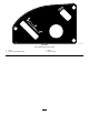
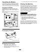
g027933
Figure4
1.Deector4.Height-of-cutlever
7.Footrest
10.Controlpanel
2.Reardrivewheel
5.Operatorseat
8.Engine11.Engineguard
3.Motion-controllevers
6.SmartSpeed™lever
9.Fuel-tankcap12.Frontcasterwheel
Controls
BecomefamiliarwithallofthecontrolsinFigure4
andFigure5beforeyoustarttheengineandoperate
themachine.
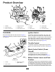
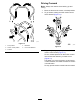
g027890
Figure5
ControlPanel
1.Throttle3.Blade-controlswitch
(powertakeoff)
2.Ignitionswitch
IgnitionSwitch
Theignitionswitchhas3positions:OFF,RUN,and
START.ThekeyturnstoSTARTandmovesbackto
RUNuponrelease.TurningthekeytotheOFFposition
stopstheengine;however,alwaysremovethekey
whenleavingthemachinetopreventsomeonefrom
accidentallystartingtheengine(Figure5).
ThrottleControl
Thethrottlecontrolstheenginespeed,andithasa
continuous-variablesettingfromSlowtoFast(Figure
5).
Blade-ControlSwitch(Power
Takeoff)
Theblade-controlswitch,representedbya
power-takeoff(PTO)symbol,engagesand
disengagespowertothemowerblades(Figure5).
Motion-ControlLeversandPark
Position
Themotion-controlleversarespeed-sensitivecontrols
ofindependentwheelmotors.Movingaleverforward
orbackwardturnsthewheelonthesamesideforward
orinreverse;thewheelspeedisproportionaltothe
amountyoumovethelever.Movethemotion-control
14