
Service Manual


ZT-2100 / ZT-2200 (EZT
®
) 13
WARNING
POTENTIAL FOR SERIOUS INJURY
Inattention to proper safety, operation, or
maintenance procedures could result in
personal injury, or damage to the equip-
ment. Before servicing or repairing the
ZT-2100 and ZT-2200 (EZT
®
), fully read
and understand the safety precautions
described in this section.
WARNING
Do not attempt any servicing or ad-
justments with the engine running.
Use extreme caution while inspecting
the drive belt assembly and all vehicle
linkage!
Follow all safety procedures outlined in
the vehicle owner’s manual.
RETURN TO NEUTRAL SETTING
The return to neutral mechanism on the trans-
mission is designed to set the directional con-
trol into a neutral position when the operator
releases the vehicle hand control. Follow the
procedures below to properly adjust the return
to neutral mechanism on the transaxle:
1. Conrm the transaxle is in the operating
mode (bypass disengaged). Raise the vehicle’s
drive tires off the ground to allow free rota-
tion.
NOTE: It may be necessary to remove the
drive wheel from the axle hub to access the
linkage control and the transaxle return arm.
Remove the wheel by removing the four (4)
lug nuts. Do not remove the axle/hub nut.
2. Remove the Original Equipment Manufactur-
er’s (OEM’s) control linkage at the control arm.
Refer to Figure 5.
3. Start the engine and increase the throttle to
full engine speed.
4. Check for axle rotation. If the axle does not
rotate, go to Step 5. If the axle rotates, go to
Step 6.
5. Stop the vehicle’s engine. Reattach and
adjust the OEM linkage according to Step 3
and Step 4. Stop the vehicle engine. Refer
to Figure 5.
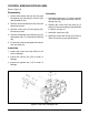
6. Note the axle directional movement. Stop
the vehicle engine. Loosen the RTN adjust-
ment screw until the control arm can be rotated.
Rotate the control arm in the opposite direction
of the wheel rotation in 5 degree increments.
Tighten the RTN adjustment screw. Refer
to table 8. Required Torque values, page 15.
Recheck according to steps 3 and 4. Stop
the vehicle engine. Reattach and adjust the
OEM linkage according to the OEM manual.
Recheck according to steps 3 and 4. Refer to
Figure 5.
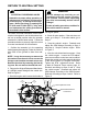
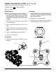
Figure 5. Return to Neutral Setting
Speed and Directional
Control Arm
RTN Adjustment Screw
15°
15°
AXLE ROTATION “B”AXLE ROTATION “A”
AXLE
ROTATION
“A”
AXLE
ROTATION
“B”