
Service Manual


16 ZT-2200 (EZT
®
)
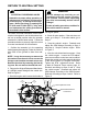
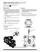
WHEEL HUB AND NUT (CODE - A, C, F, or H)
EXAMPLE: Z H
Refer to Figure 6.
Disassembly
NOTE: This procedure is only necessary if
your unit is equipped with a pin locking
nut (Figure 6a). Other units under this
code are not equipped with a pin lock-
ing nut.
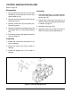
1. Place the axle so that the pin lock is at the
9 o’clock position.
2. Place a punch on the pin lock of the nut
(99).
3. Tap on the end of the punch with a rubber
mallet until the pin lock moves off of the
shaft.
4. Remove and discard the pin locking nut.
5. Remove the hub (124).
Inspection
1. Inspect the hub and axle splines for any
damage.
124
99
Pin Lock
Punch
Assembly
NOTE: Anytime a hub and/or hub nut is
removed, it must be replaced with a new
hub and/or hub nut.
1. Install hub (124) onto the shaft.
2. Install nut (99) onto shaft. Torque according
to specications in Table 8 on page 15.
Figure 6b. Pin locking nut removal.
Figure 6a. Pin locking nut.
Character 4 in the model number code = A, C, F, or H
*
*
**
**** ****
- -
-