
Service Manual

ZT-2200 (EZT
®
) 27
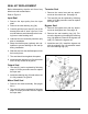
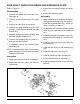
19. Reassemble the pistons, springs and thrust
washers into the cylinder block and set
aside.
20. Remove the thrust bearing assembly (35)
from the housing (1). Inspect the thrust
bearing and thrust bearing cavity in the
housing.
Inspection
1. Inspect the pump cylinder block running
surface for wear or damage.
2. Inspect the swashplate and thrust bearing
assemblies for wear or damage.
3. Inspect the center section block running
surfaces. NOTE: These “sealing” surfaces
should be smooth in appearance without
scratches, scoring, nicks or abrasions. Drag
a ngernail across the surface to detect
uneven wear or scratches which may not
be visible.
4. Inspect the threaded check plug ports of the
center section for debris or damage.
5. Inspect the motor cylinder block running
surface for damage and wear.
6. Inspect all bearing, bushing and wear areas
in the housing.
Assembly
(Motor Block)
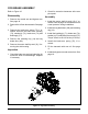
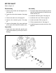
1. (See Figure 23) Turn the housing (1) so
the motor thrust bearing cavity is facing up.
This will assist in the installation of the motor
thrust bearing assembly (35) keeping it in
the bearing cavity during installation of the
center section assembly (57, Figure 21).
2. Insert the thrust bearing (35) in the housing
(1). NOTE: Place the thin race of the bear-
ing towards the housing bearing cavity. The
thick race must face the pistons.
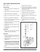
(Center Section/Filter)
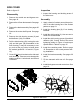
3. (See Figure 22) Install the new lter base
(61) onto the center section (57).
4. It will be necessary to clean the check plugs
prior to re-assembly. Install the check plugs
(56), in their correct location, into the center
section (57). Tighten the check plugs ac-
cording to Table 8.
5. Align the tabs on the lter cover with the
slots in the lter base and carfully press the
cover onto the base until the tabs snap into
place. Insure the bypass plate (Figure 21)
is located properly in the center section.
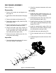
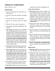
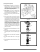
6. (See Figures 14 & 24) Install the motor
shaft (39), pinion gear (38) and at washers
(36 & 40) into the center section (57).
7. Assemble the motor block assembly (6) onto
the motor shaft (39).
8. (See Figure 22) Install the motor shaft,
center section and motor block assembly
into the housing so that the motor block
pistons contact the thrust bearing race.
NOTE: Hold in place and insure all pistons
are still positioned correctly in the cylinder
bore by conrming spring bias against the
center section.
9. (See Figure 20) After applying thread ad-
hesive, insert the center section mounting
screws (12) while holding downward pres-
sure on the center section assembly (57,
Figure 21).
10. Tighten the center section mounting screws
(12) to the proper torque. Refer to Table
8. NOTE: The center section must be fully
seated into the pilot bore before the screws
are tightened. The center section will not self
locate.
HYDRAULIC COMPONENTS