
Use and Care Manual


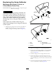

CheckingforBentBlades
Note:Themachinemustbeonalevelsurfaceforthe
followingprocedure.
1.Raisethemowerdecktothehighestheight-of-cut
position.
2.Whilewearingthicklypaddedgloves,orotheradequate
handprotection,slowlyrotatethebladetobemeasure
intoapositionthatallowseffectivemeasurementofthe
distancebetweenthecuttingedgeandthelevelsurface
themachineison(Figure51).
G014972
1
2
3
g014972
Figure51
1.Deck3.Blade
2.Spindlehousing
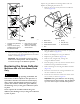
3.Measurefromthetipofthebladetotheatsurface
(Figure52).
G014973
1
2
3
g014973
Figure52
1.Blade(inpositionformeasuring)
2.Levelsurface
3.Measureddistancebetweenbladeandthesurface(A)
4.Rotatethesameblade180degreessothattheopposing
cuttingedgeisnowinthesameposition(Figure53).
G014974
1
2
3
g014974
Figure53
1.Blade(sidepreviouslymeasured)
2.Measurement(positionusedpreviously)
3.Opposingsideofbladebeingmovedintomeasurement
position
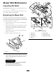
5.Measurefromthetipofthebladetotheatsurface
(Figure54).
Note:Thevarianceshouldbenomorethan3mm
(1/8inch).
G014973
1
2
3
g014973
Figure54
1.Oppositebladeedge(inpositionformeasuring)
2.Levelsurface
3.Secondmeasureddistancebetweenbladeandsurface(B)
A.IfthedifferencebetweenAandBisgreaterthan
3mm(1/8inch),replacethebladewithanew
blade;refertoRemovingtheBlades(page43)and
InstallingtheBlades(page43).
Note:Ifabentbladeisreplacedwithanew
blade,andthedimensionobtainedcontinuesto
exceed3mm(1/8inch),thebladespindlecould
bebent.ContactanAuthorizedToroDealerfor
service.
B.Ifthevarianceiswithinconstraints,movetothe
nextblade.
6.Repeatthisprocedureoneachblade.
42