
Use and Care Manual
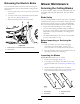
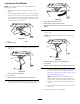
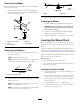
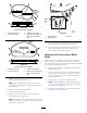
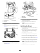
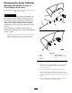

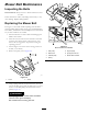
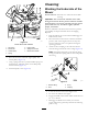
Table Of Contents
- NO TITLE
- NO TITLE
- NO TITLE
- NO TITLE
- During Operation Safety
- Operating the Mower Blade-Control Switch (PTO)
- Operating the Throttle
- Operating the Choke
- Operating the Ignition Switch
- Starting and Shutting Off the Engine
- Using the Motion-Control Levers
- Driving the Machine
- Stopping the Machine
- Adjusting the Height of Cut
- Adjusting the Anti-Scalp Rollers
- Using the Side Discharge
- NO TITLE
- NO TITLE
- NO TITLE
- NO TITLE
- NO TITLE
- NO TITLE
g017618
1
3
4
2
g017618
Figure68
1.Rodandspringassembly
installed
3.Rod,shortend,moved
behindmowerbracket
2.Loopendofthespring
installedintothenotchin
thedeectorbracket
4.Shortend,retainedby
mowerbracket.
7.Securetherodandspringassemblybytwistingitsothe
shortendoftherodisplacedbehindthefrontbracket
weldedtothedeck(Figure68).
Important:Thegrassdeectormustbespring
loadedinthedownposition.Liftthedeectorup
totestthatitsnapstothefulldownposition.
ReplacingtheGrassDeector
Machineswitha54-inchMowerDeck
Only
WARNING
Anuncovereddischargeopeningcouldallowthe
lawnmowertothrowobjectsintheoperator'sor
bystander'sdirectionandresultinseriousinjury.
Also,contactwiththebladecouldoccur.Never
operatethemachinewithoutthegrassdeector,
thedischargecover,orthegrass-collectionsystem
inplace.
Neveroperatethemachinewithoutthegrass
deector,thedischargecover,orthegrass-collection
systeminplace.
Inspectthegrassdeectorfordamagebeforeeachuse.
Replaceanydamagedpartsbeforeuse.
1.Removethenut(3/8inch)fromtherodunderthe
mower(Figure69).
G005192
1
2
3
4
5
6
7
g005192
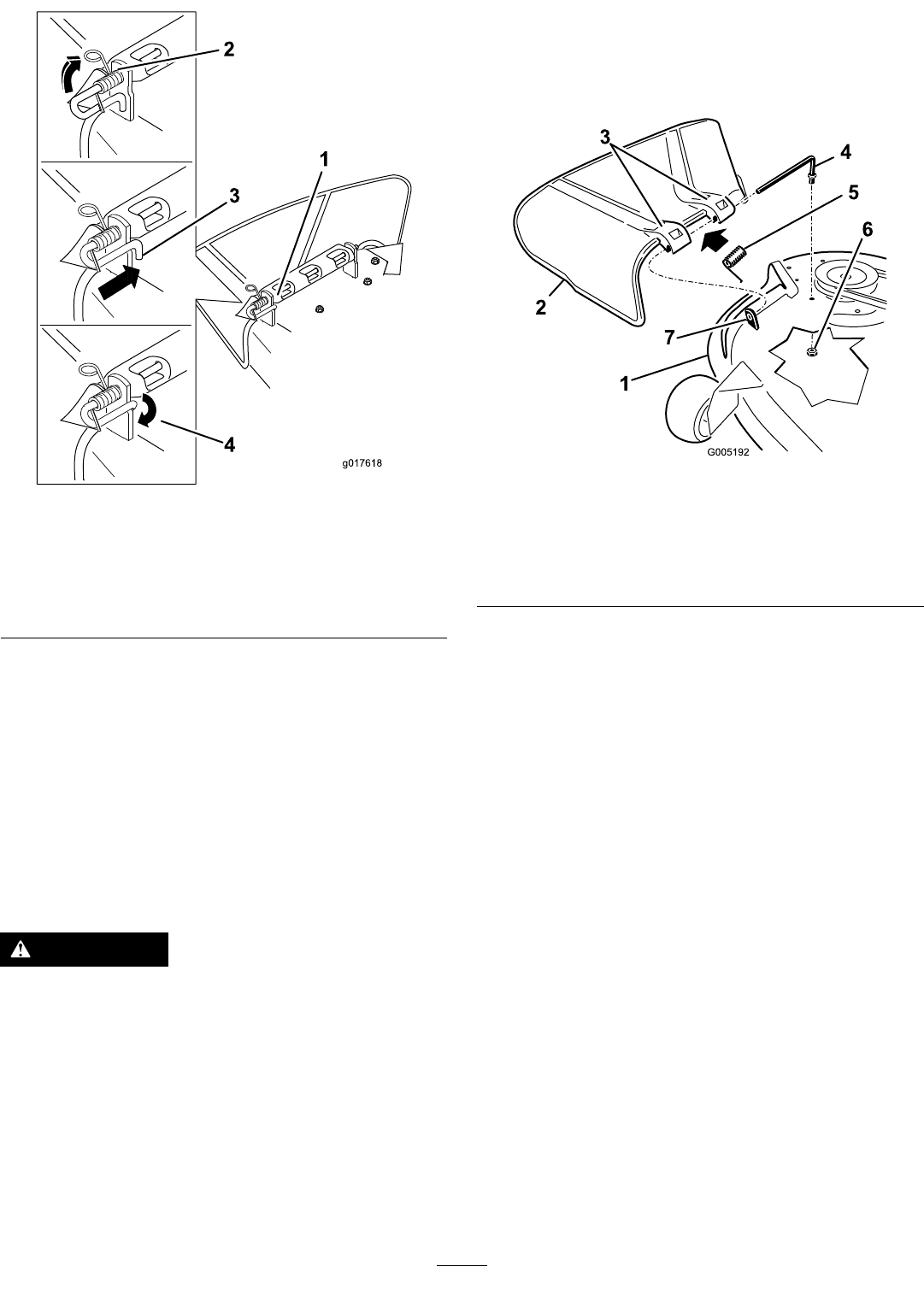
Figure69
1.Mowerdeck
5.Spring
2.Grassdeector6.Nut(3/8inch)
3.Grass-deectorbracket7.Shortstandoff
4.Rod
2.Slidetherodoutoftheshortstandoff,thespring,and
thegrassdeector(Figure69).
3.Removethedamagedorworngrassdeector.
4.Replacethegrassdeector(Figure69).
5.Slidetherod(straightend),throughthe
rear-grass-deectorbracket.
6.Placethespringontherod,withtheendwiresdown
andbetweenthegrassdeectorbrackets.
7.Sliderodthroughthesecondgrass-deectorbracket
(Figure69).
8.Inserttherodatthefrontofthegrassdeectorinto
theshortstandoffonthedeck.
9.Securetherearendoftherodintothemowerwitha
nut(3/8inch)asshowninFigure69.
Important:Thegrassdeectormustbespring
loadedandinthedownposition.Liftthedeector
uptotestthatitsnapstothefulldownposition.
48