
Service Manual

2 ZT-2100 / ZT-2200 (EZT
®
)
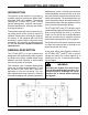
displacement control. Reversing the direction
of the swashplate reverses the ow of oil from
the pump and thus reverses the direction of the
motor output rotation. The pump and motor are
of the axial piston design and utilize spherical
nosed pistons which are held against a thrust
race by internal compression springs.
The ZT-2200 (EZT
®
) and ZT-2100 have a self
contained uid supply and an internal lter. The
uid is forced through the lter by a positive
“head” on the uid in the housing/expansion
tank with an assist by the negative pressure
created in the pump pistons as they operate.
The check valves in the center section are used
to control the make-up ow of the uid to the
low pressure side of the loop.
A cam style, block lifting bypass is utilized in
the ZT-2200 (EZT
®
) and ZT-2100 to permit
moving the vehicle for a short distance at a
maximum of 2 m.p.h. (3.2 Km/h) without start-
ing the engine.
WARNING
Actuating the bypass will result in the
loss of hydrostatic braking capacity. The
machine must be stationary on a level
surface and in neutral when actuating
the bypass.
INTRODUCTION
The purpose of this manual is to provide in-
formation useful in servicing the Hydro-Gear
®
Integrated Zero-Turn Transaxle. This manual
includes the ZT-2200 (EZT
®
) and ZT-2100
general descriptions, hydraulic schematics,
technical specications, servicing and trouble-
shooting procedures.
The transaxle normally will not require servic-
ing during the life of the vehicle in which it is
installed. Should other servicing be required,
the exterior of the transaxle will need to be
thoroughly cleaned before beginning most
procedures. Do not wash the transaxle while
it is hot. Do not use a pressure washer to
clean the unit.
GENERAL DESCRIPTION
The ZT-2200 (EZT
®
) is a self contained unit
designed for the transfer and control of power.
It provides an innitely variable speed range
between zero and maximum in both forward
and reverse modes of operation.
This transaxle uses a variable displacement
pump with a maximum displacement of 10cc
per revolution, and motor with a fixed dis-
placement of 10cc per revolution. The vari-
able displacement pump features a trunnion
mounted swashplate with a direct-proportional
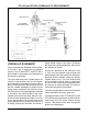
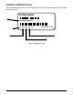
DESCRIPTION AND OPERATION
Figure 1. Hydraulic Schematic