
Service Manual

ZT-2100 / ZT-2200 (EZT
®
) 3
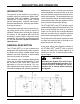
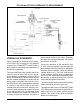
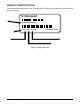
HYDRAULIC SCHEMATIC
Figure 2 provides an illustration of the hydrau-
lic oil circuit. The oil supply for the hydraulic
system of the ZT-2200 (EZT
®
) and ZT-2100 is
also utilized for lubricating the components of
the nal drive assembly.
The input shaft and pump cylinder block are
turned in one direction only by the engine/
drive belt/pulley combination. Output of the oil
ow is controlled by the direction and amount
that the variable swashplate is angled. As the
pump pistons compress they force the oil to
ow through one of two passageways (forward
or reverse) in the center section to the motor
cylinder block and motor shaft. Since the mo-
tor has a xed displacement angle it is forced
to turn with the ow of oil. As the angle of the
pump swashplate is increased the amount of
oil being pumped will increase and cause a
higher speed output of the motor. Reversing
the angle of the pump swashplate will reverse
the direction of oil ow.
During the operation of the transaxle, uid
is “lost” from the hydraulic loop through leak
paths designed into the product for lubrication
purposes (around pistons, under the rotating
cylinder blocks, etc.). This “lost” uid returns
to the transaxle housing, then is pulled back
into one of the check valves depending upon
the direction of vehicle operation. All of this oil
must pass through an internal lter.
The motor cylinder block mounts onto a splined
motor shaft which drives the gear train.
The bypass feature in the ZT-2200 (EZT
®
) and
ZT-2100 has a mechanical lever which lifts the
motor block off of the center section running
surface. This allows oil ow from the cylinder
blocks to be discharged.
Figure 2. Hydraulic Flow Illustration
ZT-2100 and ZT-2200 HYDRAULIC FLOW SCHEMATIC