Form No. 3400-836 Rev B TimeCutter® SWX 4250 or SW 5425 Riding Mower Model No. 74787—Serial No. 316000001 and Up Model No. 74793—Serial No. 316000001 and Up Register at www.Toro.com.
Introduction WARNING CALIFORNIA Proposition 65 Warning This product contains a chemical or chemicals known to the State of California to cause cancer, birth defects, or reproductive harm. The engine exhaust from this product contains chemicals known to the State of California to cause cancer, birth defects, or other reproductive harm. This machine is a ride-on, rotary-blade lawn mower intended to be used by homeowners in residential applications.
Fuel System Maintenance ................................... 37 Replacing the In-Line Fuel Filter ....................... 38 Electrical System Maintenance ........................... 38 Charging the Battery......................................... 38 Servicing the Fuses .......................................... 40 Drive System Maintenance .................................. 40 Checking the Tire Pressure............................... 40 Releasing the Electric Brake .............................
Safety • Be alert, slow down and use caution when making turns. Look behind and to the side before changing directions. To reduce the potential for injury, comply with these safety instructions and always pay attention to the safety alert symbol, which means Caution, Warning, or Danger—personal safety instruction. Failure to comply with the instruction may result in personal injury or death. • Never leave a running machine unattended.
• Follow the attachment manufacturer's • Avoid sudden starts when mowing uphill because recommendation for weight limits for towed equipment and towing on slopes. Towed weight must not exceed the weight of the machine, operator, and ballast. Use counterweights or wheel weights as described in the attachment, or in the towing machine Operator’s Manual. the mower may tip backward. • Be aware that loss of traction may occur going downhill.
Service • Never make any adjustments or repairs with the Safe Handling of Gasoline • Grass catcher components are subject to wear, engine running. damage, and deterioration, which could expose moving parts or allow objects to be thrown. Frequently check components and replace them with the manufacturers' recommended parts, when necessary. To avoid personal injury or property damage, use extra care when handling gasoline and other fuels. They are flammable and the vapors are explosive.
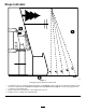
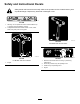
Slope Indicator g011841 Figure 3 This page may be copied for personal use. 1. The maximum slope you can safely operate the machine on is 15 degrees. Use the slope chart to determine the degree of slope of hills before operating. Do not operate this machine on a slope greater than 15 degrees. Fold along the appropriate line to match the recommended slope. 2. Align this edge with a vertical surface, a tree, building, fence pole, etc. 3.
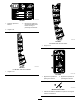
Safety and Instructional Decals Safety decals and instructions are easily visible to the operator and are located near any area of potential danger. Replace any decal that is damaged or lost. decal93-7009 93-7009 1. Warning—do not operate the mower with the deflector up or removed; keep the deflector in place. 2. Cutting/dismemberment hazard of hand or foot, mower blade—stay away from moving parts.
decal112-9840 112-9840 1. Read the Operator's Manual. 3. Remove the ignition key and read the instructions before servicing or performing maintenance. 2. Height of cut decal119-8871 119-8871 For Models with 42-inch Decks 1. Height of cut decal119-8870 119-8870 For Models with 54-inch Decks 1. Height of cut decal121-2989b 121-2989 1. Bypass lever position for pushing the machine. 2. Bypass lever position for operating the machine. decaloemmarkt Manufacturer's Mark 1.
decalbatterysymbols Battery Symbols Some or all of these symbols are on your battery 1. Explosion hazard 6. Keep bystanders a safe distance from the battery. 2. No fire, open flame, or smoking. 7. Wear eye protection; explosive gases can cause blindness and other injuries. 3. Caustic liquid/chemical burn hazard 4. Wear eye protection 8. Battery acid can cause blindness or severe burns. 9. Flush eyes immediately with water and get medical help fast. 5. Read the Operator's Manual.
decal131-3955 131-3955 For Models with 42-inch Decks decal131-3664 131-3664 For Models with 54-inch Decks 1. Spinning blade 1. On 2. Off 3. Read the Operator's Manual. 2. Reverse decal131-4036 131-4036 1. The maximum drawbar pull is 36 kg (80 lb). 2. Read the Operator's Manual. decal131-3665 131-3665 For Models with 42-inch Decks 1. Blade spinning 3. Read the Operator's Manual. 2. Reverse decal132-0872 132-0872 decal131-3954 131-3954 For Models with 54-inch Decks 1. On 2. Off 11 1.
decal132-6863 132-6863 12
decal121-0772 121-0772 For Models with 42-inch Decks 1. Fast 2. Continuous-variable setting 4. Choke 5. Power takeoff (PTO), blade-control switch 3.
decal121-0773 121-0773 For Models with 54-inch Decks 1. Fast 2. Continuous-variable setting 4. Choke 5. Power takeoff (PTO), blade-control switch 3.
decal132-0870 132-0870 1. Warning—read the Operator's Manual. 3. Bodily harm hazard—no riders; look behind you when mowing in reverse. 5. Ramp tipping hazard—when loading onto a trailer, do not use dual ramps; only use a single ramp wide enough for the machine and that has an incline less than 15 degrees; back up the ramp (in reverse) and drive forward off the ramp. 2.
Product Overview g028247 Figure 4 1. Engine 9. Anti-scalp roller 5. Key Choice® control 2. Seat 6. Mower deck 10. Deflector 3. Gas-tank cap 7. Front caster wheel 11. Height-of-cut lever 4. Steering wheel 8. Traction-control pedal 12. SmartPark™ switch 13. Rear drive wheel 14. Control panel Controls Become familiar with all controls in Figure 5 and Figure 6 before you start the engine and operate the machine. g028251 Figure 6 1. Operating-in-reverse warning light 3. Fuel-presence window 2.
Choke Control • Press the SmartPark™ switch to the ON position Use the choke to start a cold engine. Pull the choke knob up to engage it. Push down the choke knob to disengage it (Figure 5). • The parking brake engages automatically when the Throttle Control • The parking brake automatically engages 5 to 6 (Figure 5). operator leaves the seat and the traction-control pedal is in NEUTRAL position. seconds after the ignition switch is turned to the OFF position (if not already engaged).
Operation DANGER In certain conditions during fueling, static electricity can be released, causing a spark that can ignite the gasoline vapors. A fire or explosion from gasoline can burn you and others and can damage property. • Always place gasoline containers on the ground away from your vehicle before filling.
new, placing additional load on the engine. Allow 40 to 50 hours of break-in time for new machines to develop full power and best performance. Add the correct amount of gasoline stabilizer/conditioner to the gasoline. Note: A fuel stabilizer/conditioner is most effective when mixed with fresh gasoline. To minimize the chance of varnish deposits in the fuel system, use fuel stabilizer at all times. Think Safety First Please carefully read all of the safety instructions and decals in the safety section.
Testing the Safety-Interlock System CAUTION This machine produces sound levels in excess of 85 dBA at the operators ear and can cause hearing loss through extended periods of exposure. 1. Sit in the seat with the engine off and ensure that the PTO switch is in the OFF position. 2. Turn the ignition key to the START position; the starter should crank. Do not start the engine or turn the engine off prior to step 3. 3. Turn the key to the ON position and push the SmartPark switch to the OFF position.
Starting the Engine The operating-in-reverse light should turn off. Move the traction pedal to the NEUTRAL position. 16. Important: Do not engage the starter for more If not engaged, push the SmarkPark switch to the ON position and lightly tap the traction pedal in the either the FORWARD or REVERSE position. The brake should disengage and the brake light should turn off. than 5 seconds at a time. Engaging the starter motor for more than 5 seconds can damage the starter motor.
Operating the Blades Driving the Machine The blade-control switch engages and disengages power to the mower blades. This switch controls power to any attachments that draw power from the engine, including the mower deck and cutting blades. This machine has the characteristics of both a garden tractor and a zero-turn machine.
DANGER A child or bystander could be backed over by a riding mower with blades engaged and cause serious personal injury or death. • Do not mow in reverse unless absolutely necessary. • Always look backward and down before backing up. g027750 Figure 14 1. Forward 2. Traction-control pedal 4. • Use the KeyChoice switch only if you are certain no children or other bystanders will appear in the mowing area. 3.
Positioning the Seat The seat can move forward and backward. Position the seat where you have the best control of the machine and are most comfortable. g027632 Figure 16 Positioning the Steering Wheel g028025 Figure 15 The steering wheel has 3 positions for operation and 1 full-up position. Use the full-up position for stepping on and off the machine and getting out of the seat.
Adjusting the Anti-scalp Rollers 42-inch Mower Decks Only Whenever you change the height of cut, adjust the height of the anti-scalp rollers. Note: Adjust the anti-scalp rollers so the rollers do not touch the ground in normal, flat mowing areas. 1. Disengage the blade-control switch (PTO) and engage the parking brake. 2. Shut off the engine, remove the key, and wait for all moving parts to stop before leaving the operating position. 3.
Adjusting the Anti-scalp Rollers 4. Move the bypass levers forward through the key hole and down to lock them in place (Figure 20). 5. Turn the ignition key to the ON position and disengage the parking brake. 54-inch Mower Decks Only Note: Do not start the machine. Whenever you change the height of cut, adjust the height of the anti-scalp rollers. Note: Adjust the anti-scalp rollers so the rollers do not touch the ground in normal, flat mowing areas. 1.
Using the Grass Deflector 5. The mower has a hinged grass deflector that disperses clippings to the side and down toward the turf. Tie down the machine near the front caster wheels and the rear bumper (Figure 21). Note: Avoid the steering components and mower deck parts when tying down the machine at the front caster wheels. DANGER Without the grass deflector, discharge cover, or complete grass catcher assembly mounted in place, you and others are exposed to blade contact and thrown debris.
WARNING Loading a machine onto a trailer or truck increases the possibility of tip-over and could cause serious injury or death. • Use extreme caution when operating a machine on a ramp. • Use only a full-width ramp; do not use individual ramps for each side of the machine. • Do not exceed a 15-degree angle between the ramp and the ground or between the ramp and the trailer or truck. • Ensure that the length of ramp is at least 4 times as long as the height of the trailer or truck bed to the ground.
Operating Tips raise the cutting height higher than usual and cut the grass at this setting. Then cut the grass again using the lower, normal setting. Using the Fast Throttle Setting For best mowing and maximum air circulation, operate the engine at the FAST position. Air is required to thoroughly cut grass clippings, so do not set the height-of-cut so low as to totally surround the mower in uncut grass.
Maintenance Note: Determine the left and right sides of the machine from the normal operating position. Recommended Maintenance Schedule(s) Maintenance Service Interval Maintenance Procedure After the first 5 hours • Change the engine oil. Before each use or daily • • • • • Check the engine-oil level. Clean the air intake screen. Check the cutting blades. Inspect the grass deflector for damage. Inspect the grass deflector for damage. After each use • Check and clean the front of the mower.
Pre-Maintenance Procedures Lubrication Raising the Seat Service Interval: Every 25 hours—Grease all the lubrication points. Greasing the Bearings Engage the parking brake and lift the seat forward. Grease Type: No. 2 lithium grease You can access the following components by raising the seat: • Serial plate 1. Park the machine on a level surface, and disengage the blade-control switch. 2.
Engine Maintenance Servicing the Air Cleaner Note: Service the air cleaner more frequently (every few hours) if operating conditions are extremely dusty or sandy. g027802 Figure 28 Removing the Elements 1. Park the machine on a level surface and disengage the blade-control switch (PTO). 2. Engage the parking brake, shut off the engine, remove the key, and wait for all moving parts to stop before leaving the operating position. 3. 4.
Servicing the Engine Oil Oil Type: Detergent oil (API service SF, SG, SH, SJ, or SL) Crankcase Capacity: 2.4 L (2.5 US qt) Viscosity: See the table below. g029683 Figure 29 Checking the Engine-Oil Level Service Interval: Before each use or daily Note: Check the oil when the engine is cold. WARNING Contact with hot surfaces may cause personal injury. g029368 Figure 30 Keep hands, feet, face, clothing, and other body parts away the muffler and other hot surfaces.
4. Drain the engine oil.
5. Change the engine oil filter (Figure 32). g027484 Figure 33 Servicing the Spark Plug g027477 Service Interval: Every 100 hours/Yearly (whichever comes first)—Check the spark plug(s). Figure 32 Note: Ensure that the oil-filter gasket touches Every 200 hours/Every 2 years (whichever comes first)—Replace the spark plug(s). the engine and then turn the filter an extra 3/4 turn. 6. Make sure that the air gap between the center and side electrodes is correct before installing the spark plug.
g027478 Figure 34 Note: Due to the deep recess around the spark plug, blowing out the cavity with compressed air is usually the most effective method for cleaning. The spark plug is most accessible when the blower housing is removed for cleaning. g027960 Figure 36 Checking the Spark Plug Important: Do not clean the spark plug(s). Always replace the spark plug(s) when it has: a black coating, worn electrodes, an oily film, or cracks.
Cleaning the Cooling System Fuel System Maintenance Clean the air intake screen from grass and debris before each use. 1. Disengage the blade-control switch and engage the parking brake. 2. Shut off the engine, remove the key, and wait for all moving parts to stop before leaving the operating position. 3. Remove the air filter from the engine. 4. Remove the engine shroud. 5. To prevent debris entering the air intake, install the air filter to the filter base. 6.
Replacing the In-Line Fuel Filter Electrical System Maintenance Service Interval: Every 100 hours/Yearly (whichever comes first)—Check the in-line fuel filter. WARNING CALIFORNIA Proposition 65 Warning Battery posts, terminals, and related accessories contain lead and lead compounds, chemicals known to the State of California to cause cancer and reproductive harm. Wash hands after handling. Every 200 hours/Every 2 years (whichever comes first)—Replace the in-line fuel filter.
3. WARNING Incorrect battery cable routing could damage the machine and cables causing sparks. Sparks can cause the battery gasses to explode, resulting in personal injury. • Always disconnect the negative (black) battery cable before disconnecting the positive (red) cable. • Always connect the positive (red) battery cable before connecting the negative (black) cable.
Servicing the Fuses Drive System Maintenance The electrical system is protected by fuses. It requires no maintenance; however, if a fuse blows, check the component or circuit for a malfunction or short. Checking the Tire Pressure Fuse type: • Main—F1-30 A, blade-type Service Interval: Every 25 hours—Check the tire pressure. • Charge Circuit—F2-25 A, blade-type 1. Maintain the air pressure in the front and rear tires as specified. Uneven tire pressure can cause uneven cut.
Mower Maintenance Releasing the Electric Brake Servicing the Cutting Blades The electric brake can be release by manually rotating the link arms forward. Once the electric brake is energized, the brake will reset. Maintain sharp and balanced blades throughout the cutting season, because sharp blades cut cleanly without tearing or shredding the grass blades. Tearing and shredding turns grass brown at the edges, which slows growth, and increases the chance of disease.
3. Measure from the tip of the blade to the flat surface (Figure 45). g006530 Figure 43 1. Cutting edge 3. Wear/slot forming 2. Curved area 4. Damage g014973 Figure 45 Checking for Bent Blades 1. Blade (in position for measuring) Note: The machine must be on a level surface for the following procedure. 2. Level surface 3. Measured distance between blade and the surface (A) 1. 2. Raise the mower deck to the highest height-of-cut position, also considered the ‘transport’ position. 4.
g000551 Figure 48 g014973 Figure 47 1. Sail area of the blade 2. Blade 1. Opposite blade edge (in position for measuring) 3. Curved washer 4. Blade bolt 2. Level surface 3. Second measured distance between blade and surface (B) Sharpening the Blades 1. WARNING A blade that is bent or damaged could break apart and could seriously injure or kill you or bystanders. Use a file to sharpen the cutting edge at both ends of the blade (Figure 49). Note: Maintain the original angle.
Installing the Blades 1. Install the blade onto the spindle shaft (Figure 48). Important: The curved part of the blade must be pointing upward toward the inside of the mower to ensure proper cutting. 2. Install the curved washer (cupped side toward the blade) and the blade bolt (Figure 48). 3. Torque the blade bolt to 47 to 88 N∙m (35 to 65 ft-lb).
g009658 Figure 54 Mower Decks with 2 Blades 1. Blades front to rear 2. Measure from the tip of the blade to the flat surface here. g027588 Figure 53 1. Hanger bracket 3. Rear nut 2. Side locking nut 9. Check the side-to-side adjustments again. Repeat this procedure until the measurements are correct. 10. Continue leveling the mower deck by checking the front-to-rear blade slope; refer to Adjusting the Front-to-Rear Blade Slope (page 45). g009659 Figure 55 Mower Decks with 3 Blades 1.
g014634 Figure 56 1. Adjusting rod 3. Locknut 2. Adjusting block g014635 7. Figure 57 To raise the front of the mower, tighten the adjustment nut. 1. Front support rod 8. To lower the front of the mower, loosen the adjustment nut. 2. Locking nut 9. After adjustment, check the front-to-rear slope again, continue adjusting the nut until the front blade tip is 1.6 to 7.9 mm (1/16 to 5/16 inch) lower than the rear blade tip (Figure 54 and Figure 55). 5. 10.
Note: Retain all parts for future installation. Mower Belt Maintenance Inspecting the Belts Service Interval: Every 25 hours—Check the belts for wear/cracks. Check the belts for cracks, frayed edges, burn marks, or any other damage. Replace damaged belts. Replacing the Mower-Deck Belt Squealing when the belt is rotating, blades slipping when cutting grass, frayed belt edges, burn marks, and cracks are signs of a worn mower belt. Replace the mower belt if any of these conditions are evident. 1.
Replacing the Grass Deflector Model 74787 Only Service Interval: Before each use or daily—Inspect the grass deflector for damage. WARNING An uncovered discharge opening could allow the lawn mower to throw objects at you or bystanders and result in serious injury. Also, contact with the blade could occur. Never operate the lawn mower unless you install a mulch plate, discharge deflector, or grass collection system. g014931 Inspect the grass deflector for damage before each use.
g017618 Figure 63 1. Rod and spring assembly installed 2. Loop end of the spring installed into the notch in the deflector bracket 3. Rod, short end, moved behind mower bracket 4. Short end, retained by mower bracket. g032884 Figure 62 1. Rod 2. Spring 5. 4. Deck brackets 5. Spring installed over the rod 3. Deflector 2. Position the new discharge deflector with the bracket ends between the welded brackets on the deck as shown in Figure 63. 3. Install the spring onto the straight end of the rod.
Important: The grass deflector must be spring-loaded and in the down position. Lift the deflector up to test that it snaps to the full down position. WARNING An uncovered discharge opening could allow the lawn mower to throw objects at you or bystanders, resulting in serious injury. Also, contact with the blade could occur. Never operate the machine without the grass deflector, the discharge cover, or the grass-collection system in place. Inspect the grass deflector for damage before each use.
Cleaning Cleaning under the Front of the Machine Service Interval: After each use—Check and clean the front of the mower. Remove debris under the front of the machine with compressed air or by hand with a brush (Figure 65). Note: Do not use water to clean under the front of the machine, this can cause build up of debris. g020098 Figure 66 g028248 Figure 65 1. Washout fitting 3. O-ring 2. Hose 4. Coupling 4. Lower the mower to the lowest height of cut. 5. Sit on the seat and start the engine.
Storage 12. Clean any dirt and chaff from the top of the mower. Cleaning and Storage 13. Scrape any heavy buildup of grass and dirt from the underside of the mower, then wash the mower with a garden hose. 14. Check the condition of the drive and mower belts. 15. Check and tighten all bolts, nuts, and screws. Repair or replace any part that is worn or damaged. 16. Paint all scratched or bare metal surfaces. Paint is available from your Authorized Service Dealer. 17.
Troubleshooting Problem The engine overheats. Possible Cause 1. The engine load is excessive. 1. Reduce ground speed. 2. The oil level in the crankcase is low. 3. The cooling fins and air passages under the engine blower housing are plugged. 4. The air cleaner is dirty. 2. Add oil to the crankcase. 3. Remove the obstruction from the cooling fins and air passages. 5. Dirt, water, or stale fuel is in fuel system. The starter does not crank.
Problem There is abnormal vibration. The cutting height is uneven. Possible Cause 1. The engine mounting bolts are loose. 1. Tighten the engine mounting bolts. 2. The engine pulley, idler pulley, or blade pulley is loose. 3. The engine pulley is damaged. 4. The cutting blade(s) is/are bent or unbalanced. 5. A blade mounting bolt is loose. 6. A blade spindle is bent. 2. Tighten the appropriate pulley. 5. Tighten the blade mounting bolt. 6. Contact an Authorized Service Dealer. 1.
Schematics g027754 Electrical Diagram (Rev.
TimeCutter and TITAN Mowers The Toro Warranty Limited Warranty (see warranty periods below) Conditions and Products Covered The Toro Company and its affiliate, Toro Warranty Company, pursuant to an agreement between them, jointly promise to repair the Toro Products listed below if defective in materials or workmanship. 1. Contact any Authorized Toro Service Dealer to arrange service at their dealership. To locate a dealer convenient to you, access our web site at www.Toro.com.