
Setup Instructions


upper3/8x1inchboltandspringdiscwasherinthe
controlleversothatthelevercanrotate(Figure2).
2.Positiontheleversothebottomholealignswith
holeinthecontrolarmshaft.Installspringdisc
washerandbolt.
3.Repeatonoppositesideofunit.
Note:Therearetwoleverheightoptionsavailable.
Placetheleversinthetoptwoholestoincrease
heightofthelevers,orinthebottomtwoholesto
decreasetheheightofthelevers.
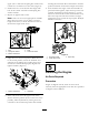
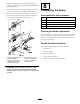
Figure2
1.Bolt
4.Seat
2.Springdiscwasher5.Controlarmshaft
3.Motioncontrollever
4.Aligntheleversfront/rearposition.Withthelevers
intheneutralposition,loosenthehardwareand
adjusttheleversslidingand/ortiltingthelever(s)
forwardorbackwarduntilproperlyalignedand
tightenhardware(Figure3).
Figure3
1.Motioncontrollever2.Hardware
5.Iftheendsofthelevershitagainsteachother,
whileinthedriveposition(leversrotatedinasfaras
possible),makeadjustmentsbymovingthelevers
outwardstotheneutrallockpositionandcarefully
bendingthemoutward.Movethembacktothedrive
positionandcheckforclearance.Repeatifnecessary.
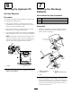
6.Ifthemachineturnsrightorleftwhenhandlesare
pushedforwardtogether,adjustthestopontheside
oppositethedirectionofturn(Figure4).Loosen
thescrewsthatholdthemotioncontrollimiterstop.
Movethestopbackuntiltheunitdrivesstraight.
Tightenthescrewstolockthestopinplace.Readjust
handlesifnecessary.
Figure4
1.Controlarmshaft
3.Adjuststop
2.Limiterstopscrews
5
ServicingtheEngine
NoPartsRequired
Procedure
Engineisshippedwithoil;checkoillevelandif
necessarylltotheappropriatelevelwithoilasspecied
inEngineOwner’sManual.
3