
Setup Instructions
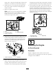


3.Installthespringandrodassemblythroughthe
openingsinboththedeckbracketsandthedeector
bracket(Figure6).
4.Liftthelongendofthespringandplaceitintothe
notchonthedeectorassemblybracket(Figure7).
5.Securetherodandspringassemblybytwistingitso
theshortendoftherodcanbeplacedbehindthe
frontbracketweldedtothedeck(Figure7).
G006049
1
2
3
4
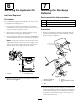
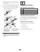
Figure7
1.Rodandspringassembly
partiallyinstalled
3.Rod,shortend,moved
behindmowerbracket
2.Longendofthespring
installedintothenotchin
thedeectorbracket
4.Shortend,retainedby
mowerbracket.
Important:Thedischargedeectormustbe
springloadedinthedownposition.Liftthe
deectoruptotestthatitsnapstothefulldown
position.
8
CompletingtheSetup
Partsneededforthisprocedure:
1IgnitionKey
1Hosecoupling
1
Operator’sManual
1
EngineOperator’sManual
1
OperatorTrainingMaterial
CheckingtheMowerAdjustment
Themowerdeckwasleveledatthefactory.Ifthemower
isnotcuttinglevel,adjusttheside-to-sidelevelandthe
front-to-rearbladeslope.SeetheOperator’sManualfor
theproperprocedure.
ReviewtheRemainingParts
Keepallthefollowingitemswiththemachine:
•IgnitionKey
•Hosecoupling
•Operator’sManual
•EngineOperator’sManual
•ViewtheOperatortrainingmaterial.
5