Form No. 3410-275 Rev B TimeCutter® HD XS4850 and X5450 Riding Mower Model No. 74866—Serial No. 400000000 and Up Model No. 74867—Serial No. 400000000 and Up Register at www.Toro.com.
model and serial numbers on the product. Write the numbers in the space provided. WARNING CALIFORNIA Proposition 65 Warning This product contains a chemical or chemicals known to the State of California to cause cancer, birth defects, or reproductive harm. The engine exhaust from this product contains chemicals known to the State of California to cause cancer, birth defects, or other reproductive harm.
Mower Belt Maintenance ............................................49 Inspecting the Belts ................................................49 Replacing the Mower Belt ........................................49 Cleaning ...................................................................50 Washing the Underside of the Mower ........................50 Cleaning the Suspension System ...............................51 Disposing of Waste.................................................51 Storage ..................
Safety This machine has been designed in accordance with EN ISO 5395:2013. General Safety This product is capable of amputating hands and feet and of throwing objects. Always follow all safety instructions to avoid serious personal injury. Using this product for purposes other than its intended use could prove dangerous to you and bystanders. • Read and understand the contents of this Operator’s Manual before you start the engine.
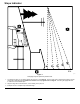
Slope Indicator G011841 g011841 Figure 3 This page may be copied for personal use. 1. The maximum slope you can safely operate the machine on is 15 degrees. Use the slope chart to determine the degree of slope of hills before operating. Do not operate this machine on a slope greater than 15 degrees. Fold along the appropriate line to match the recommended slope. 2. Align this edge with a vertical surface, a tree, building, fence pole, etc. 3.
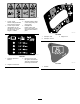
Safety and Instructional Decals Safety decals and instructions are easily visible to the operator and are located near any area of potential danger. Replace any decal that is damaged or missing. decaloemmarkt Manufacturer's Mark 1. Indicates the blade is identified as a part from the original machine manufacturer. decalbatterysymbols Battery Symbols Some or all of these symbols are on your battery. 1. Explosion hazard 6. Keep bystanders a safe distance away from the battery. 2.
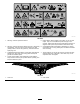
decal132-0872 132-0872 1. Thrown object hazard—keep bystanders away from the machine. 3. Severing hazard of hand or foot—keep away from moving parts. 2. Thrown object hazard, raised baffle—do not operate the machine with an open deck; use a bagger or a baffle. 4. Entanglement hazard—keep away from moving parts; keep all guards and shields in place. decal130-0654 130-0654 1. Transport—lock 3. Height of cut 2. Transport—unlock decal130-0765 130-0765 1. Read the Operator's Manual. 3.
decal132-0869 132-0869 1. Warning—read the Operator's Manual. 5. Ramp hazard—When loading onto a trailer, do not use split ramps. Only use a full-width ramp wide enough for the machine. Ramp angle with the ground should be less than 15 degrees. Back up the ramp and drive forward off the ramp. 2. Warning—read the instructions before servicing or performing maintenance; move the motion-control levers to the park (brake) position, remove the ignition key, and disconnect the spark-plug wire. 6.
decal133-9263 133-9263 1. Fast 4. PTO disengage 2. Slow 5. PTO engage 3. Choke decal136-4243 136-4243 1. Fast 2. Slow 4. Reverse 5. Parking brake disengaged 3. Neutral 6. Parking brake engaged decal136-4245 136-4245 1. Slow 2. Transport decal136-4244 136-4244 1. Fast 2. Slow 3. Neutral 4. Reverse 9 3.
decal136-5596 136-5596 1. Check the tire pressure every 25 operating hours. 4. Check the tire pressure every 25 operating hours. 2. Engine oil 5. Read the Operator's Manual before performing maintenance. 3. Check the tire pressure every 25 operating hours. decal136-9186 136-9186 1. Read the Operator's Manual before adding weight to the bucket.
Controls Product Overview Become familiar with all controls in Figure 5 and Figure 6 before you start the engine and operate the machine. g188738 Figure 5 1. Hour meter 4. Ignition switch 2. Throttle control 3. Choke control 5. PTO switch 6. 12 V power point g195717 Figure 4 1. Deck-lift pedal 7. Engine 2. Height-of-cut pin 8. Fuel cap 3. Height-of-cut lever/transport lock 9. Mower deck 4. Smart Speed™ lever 10. Anti-scalp roller 5. Motion-control lever 6. Controls 11. Caster wheel 12.
Choke Control Blade-Control Switch (Power Takeoff) Use the choke control to start a cold engine. Pull the choke control up to engage it. Push down on the choke control to disengage it. The blade-control switch (PTO) engages and disengages power to the mower blades (Figure 5). Height-of-Cut Lever Hour Meter The height-of-cut lever works with the foot pedal to lock the deck in a specific cutting height. Only adjust the height of cut while machine is not moving (Figure 4).
Operation • Do not operate the machine without the entire exhaust Note: Determine the left and right sides of the machine from the normal operating position. • Before Operation • • Before Operation Safety • General Safety • Never allow children or untrained people to operate or • • • • • • • service the machine. Local regulations may restrict the age of the operator. The owner is responsible for training all operators and mechanics.
Breaking in a New Machine Add the correct amount of fuel stabilizer/conditioner to the fuel. New engines take time to develop full power. Mower decks and drive systems have higher friction when new, placing additional load on the engine. Allow 40 to 50 hours of break-in time for new machines to develop full power and best performance. Note: A fuel stabilizer/conditioner is most effective when mixed with fresh fuel.
1. Sit on the seat, engage the parking brake, and move the blade-control switch (PTO) to the ON position. Try starting the engine; the engine should not crank. CAUTION This machine produces sound levels in excess of 85 dBA at the operator’s ear and can cause hearing loss through extended periods of exposure. 2. Sit on the seat, engage the parking brake, and move the blade-control switch (PTO) to the OFF position. Move either motion-control lever (out of the NEUTRAL-LOCK position).
Adjusting the MyRide™ Suspension System Adjust the rear-shock assemblies (Figure 12). The MyRide™ suspension system adjusts to provide a smooth and comfortable ride. Adjusting the rear 2-shock assemblies is the easiest and quickest adjustment for changing the suspension system. Position the suspension system where you are most comfortable. Adjusting the Rear-Shock Assemblies g195746 The slots for the rear-shock assemblies have detent positions for reference.
Adjusting the Motion-Control Levers During Operation During Operation Safety Adjusting the Height General Safety You can adjust the motion-control levers higher or lower for maximum comfort (Figure 13). A • The owner/operator can prevent and is responsible for B • • • • • g027252 g027252 Figure 13 • Adjusting the Tilt • You can adjust the motion-control levers forward or rearward for your comfort. • 1. Loosen the upper bolt holding the control lever to the control-arm shaft. • 2.
Operating the Parking Brake – Wait for all moving parts to stop. • Do not operate the machine when there is the risk of Always engage the parking brake when you stop the machine or leave it unattended. lightning. • Do not use the machine as a towing vehicle. Engaging the Parking Brake • Do not change the governor speed or overspeed the engine. WARNING • Use accessories and attachments approved by Toro only.
Operating the Mower Blade-Control Switch (PTO) Operating the Throttle You can move the throttle control between the FAST and SLOW positions (Figure 19). The blade-control switch (PTO) starts and stops the mower blades and any powered attachments. Always use the FAST position when turning on the mower deck with the blade-control switch (PTO).
Starting and Shutting Off the Engine Operating the Ignition Switch 1. Turn the ignition key to the START position (Figure 21). Note: When the engines starts, release the key. Starting the Engine Important: Do not engage starter for more than 5 seconds at a time. If the engine fails to start, allow a 15 second cool-down period between attempts. Failure to follow these instructions can burn out the starter motor. Note: A warm or hot engine may not require choking.
Driving Forward Using the Motion-Control Levers Note: The engine stops when you move the traction-control with the parking brake engaged. To stop, pull the motion-control levers to the NEUTRAL position. 1. Disengage the parking brake; refer to Disengaging the Parking Brake (page 18). 2. Move the levers to the center, unlocked position. 3. To go forward, slowly push the motion-control levers forward (Figure 24). g004532 Figure 23 1. Motion-control lever—NEUTRAL-LOCK position 4. Backward 2.
Driving Backward The following are only recommendations for use. Adjustments vary by grass type, moisture content, and the height of the grass. 1. Move the levers to the center, unlocked position. 2. To go backward, slowly pull the motion-control levers rearward (Figure 25). Suggested uses: Trim Parking X Heavy, wet grass X Training X Tow Bagging X Mulching X Mow Normal mowing X Transport X Trim This is the lowest speed.
Using the Side Discharge Adjusting the Height of Cut The mower has a hinged grass deflector that disperses clippings to the side and down toward the turf. The machine is equipped with a foot pedal deck-lift system. You can use the foot pedal to lift the deck briefly to avoid obstacles or lock the deck in the highest height of cut or transport position. You can use the height-of-cut lever with the foot pedal to lock the deck in a specific cutting height.
4. Push on the deck-lift pedal with your foot and pull the handle rearward to disengage the transport lock (Figure 27). Adjusting the Anti-Scalp Rollers 5. Lower the deck slowly until the lever makes contact with the pin. Whenever you change the height-of-cut, it is recommended to adjust the height of the anti-scalp rollers. 1. Disengage the blade-control switch (PTO), move the motion-control levers to the NEUTRAL-LOCK position, and engage the parking brake. 2.
2. Move the motion-control levers outward to the NEUTRAL-LOCK position, engage the parking brake, shut off the engine, remove the key, and wait for all moving parts to stop before leaving the operating position. 8. Remove the 2 locknuts (5/16 inch) to securing the welded posts of the right baffle to the top of the mower deck at the center and right of center positions (Figure 32). Note: Remove the right baffle from the mower deck. 3. Remove the mower deck; refer to Removing the Mower Deck (page 47).
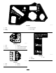
11. Use the fasteners removed to secure the cutoff baffle to the deck. 5. Remove the carriage bolt and locknut on the side wall of the mower deck securing the left baffle to the deck (Figure 34). 12. Install the mower deck; refer to Installing the Mower Deck (page 48). 6. Remove the left baffle from the mower deck (Figure 34). Converting the 54-inch Mower Deck to Side Discharge 7.
1 2 G010704 3 g190737 Figure 35 1. Locknuts—front of discharge plate (install after baffle is removed) 5. Baffle guard—54-inch decks 2. Hex-head bolt—forward hole in deck (install after baffle is removed) 6. Locknut (5/16 inch) 3. Locknut—forward hole in deck (install after baffle is removed) 7. Carriage bolt (5/16 x 3/4 inch) g010704 Figure 36 1. Locknut (5/16 inch) 3. Welded posts (right baffle) 2. Right baffle 12.
15. Use the fasteners removed to secure the cutoff baffle to the deck. Operating Tips 16. Install the mower deck; refer to Installing the Mower Deck (page 48). Using the Fast Throttle Setting For best mowing and maximum air circulation, operate the engine at the FAST position. Air is required to thoroughly cut grass clippings, so do not set the height-of-cut so low as to totally surround the mower in uncut grass.
Keeping the Underside of the Mower Clean After Operation Clean clippings and dirt from the underside of the mower after each use. If grass and dirt build up inside the mower, cutting quality will eventually become unsatisfactory. After Operation Safety General Safety Maintaining the Blade(s) • Clean grass and debris from the cutting units, mufflers, and engine compartment to help prevent fires. Clean up oil or fuel spills.
Pushing the Machine by Hand Transporting the Machine Important: Always push the machine by hand. Do not tow the machine, because damage may occur. Use a heavy-duty trailer or truck to transport the machine. Ensure that the trailer or truck has all necessary brakes, lighting, and marking as required by law. Please carefully read all the safety instructions. Knowing this information could help you, your family, pets, or bystanders avoid injury. Pushing the Machine 1.
Loading the Machine 1 Use extreme caution when loading or unloading machines onto a trailer or a truck. Use a full-width ramp that is wider than the machine for this procedure. Back the machine up the ramp and drive it forward down the ramp (Figure 40). g027995 Figure 40 1. Back the machine up the ramp. 2 2. Drive the machine forward down the ramp. Important: Do not use narrow individual ramps for each side of the machine.
Maintenance Note: Determine the left and right sides of the machine from the normal operating position. Recommended Maintenance Schedule(s) Maintenance Service Interval Maintenance Procedure After the first 5 hours • Change the engine oil. Before each use or daily • • • • • • Check the safety-interlock system. Check the air cleaner for dirty, loose, or damaged parts. Check the engine-oil level. Clean the air intake screen. Inspect the blades. Inspect the grass deflector for damage.
Pre-Maintenance Procedures Releasing the Mower-Deck Curtain Loosen the 2 bottom bolts of the curtain to access the top of the mower deck (Figure 42). Maintenance and Storage Safety • Before repairing the machine do the following: – Disengage the drives. – Engage the parking brake. – Shut off the engine and remove the key. – Disconnect the spark-plug wire. • Park the machine on a level surface. • Clean grass and debris from the cutting unit, drives, mufflers, and engine to help prevent fires.
Engine Maintenance WARNING Contact with hot surfaces may cause personal injury. Keep your hands, feet, face, clothing, and other body parts away the muffler and other hot surfaces. g027800 Engine Safety g027800 Shut off the engine before checking the oil or adding oil to the crankcase. Servicing the Air Cleaner Service Interval: Before each use or daily Note: Service the air cleaner more frequently (every few hours) if operating conditions are extremely dusty or sandy. Removing the Elements 1.
Servicing the Paper Element 1. Park the machine on a level surface, disengage the blade-control switch, shut off the engine, engage parking brake, and remove the key. Service Interval: Every 100 hours/Yearly (whichever comes first)—Service the air-cleaner paper element (more often in dusty, dirty conditions). 2. Make sure that the engine is shut off, level, and is cool, so that the oil has had time to drain into the sump. 3. To keep dirt, grass clippings, etc.
Changing the Engine Oil and Oil Filter Service Interval: After the first 5 hours/After the first month (whichever comes first)—Change the engine oil. Every 100 hours/Yearly (whichever comes first)—Change the engine oil (more often in dusty, dirty conditions). Every 100 hours/Yearly (whichever comes first)—Change the oil filter (more often in dusty, dirty conditions). g027799 g027799 Note: Change the engine-oil filter more frequently when operating conditions are extremely dusty or sandy.
5. Change the engine-oil filter (Figure 48). Note: Ensure that the oil-filter gasket touches the engine and then turn the filter an extra 3/4 turn. A B C D E F g193530 Figure 49 Servicing the Spark Plug Service Interval: Every 100 hours/Yearly (whichever comes first)—Check the spark plug(s). 3/4 g027477 Every 200 hours/Every 2 years (whichever comes first)—Replace the spark plug(s).
A Installing the Spark Plug B Tighten the spark plug(s) to 25 to 30 N∙m (18.5 to 22.1 ft-lb). B A g027478 g027478 Figure 50 Note: Due to the deep recess around the spark plug, blowing out the cavity with compressed air is the most effective method for cleaning. The spark plug is most accessible when the blower housing is removed for cleaning. C 25-30 N-m 18.5-22.1 ft-lb D Checking the Spark Plug g027960 Important: Do not clean the spark plug(s).
Fuel System Maintenance DANGER In certain conditions, fuel is extremely flammable and highly explosive. A fire or explosion from fuel can burn you, others, and can damage property. g027939 g027939 • Perform any fuel-related maintenance when the engine is cold. Do this outdoors in an open area. Wipe up any fuel that spills. • Never smoke when draining fuel, and stay away from an open flame or where a spark may ignite the fuel fumes.
Electrical System Maintenance Electrical System Safety • Disconnect the battery before repairing the machine. Disconnect the negative terminal first and the positive last. Connect the positive terminal first and the negative last. • Charge the battery in an open, well-ventilated area, away from sparks and flames. Unplug the charger before connecting or disconnecting the battery. Wear protective clothing and use insulated tools. g190587 Figure 54 1. Battery cover WARNING 2. Fasteners 4.
Installing the Battery 1. Position the battery in the tray (Figure 55). 2. Using the fasteners previously removed, install the positive (red) battery cable to the positive (+) battery terminal. 3. Using the fasteners previously removed, install the negative battery cable to the negative (-) battery terminal. 4. Slide the red terminal boot onto the positive (red) battery post. 5. Secure the battery with the hold-down (Figure 55). 6.
Servicing the Fuses Drive System Maintenance The electrical system is protected by fuses. It requires no maintenance; however, if a fuse blows, check the component/circuit for a malfunction or short. Fuse type: Checking the Tire Pressure • Main—F1 (15 A, blade-type) Service Interval: Every 25 hours—Check tire pressure. • Charge Circuit—F2 (25 A, blade-type) Maintain the air pressure in the front and rear tires as specified. Uneven tire pressure can cause uneven cut.
Mower Maintenance Checking for Bent Blades Note: The machine must be on a level surface for the following procedure. Servicing the Cutting Blades 1. Raise the mower deck to the highest height-of-cut position. To ensure a superior quality of cut, keep the blades sharp. For convenient sharpening and replacement, keep extra blades on hand. 2.
Removing the Blades The blades must be replaced if a solid object is hit, if the blade is out of balance, or if the blade is bent. For best performance and continued safety conformance of the machine, use genuine Toro replacement blades. Replacement blades made by other manufacturers may result in non-conformance with safety standards. 3 2 1 1. Hold the blade end using a rag or thickly padded glove. G014974 2. Remove the blade bolt, curved washer, and blade from the spindle shaft (Figure 65).
Leveling the Mower Deck Note: If the blade is not balanced, file some metal off the end of the sail area only (Figure 66). Ensure that the mower deck is level any time you install the mower deck or when you see an uneven cut on your lawn. Check the mower deck for bent blades prior to leveling; remove and replace any bent blades; refer to Checking for Bent Blades (page 43) before continuing. g000553 Figure 67 1. Blade Level the mower deck side-to-side before adjusting the front-to-rear slope. 2.
Leveling the Mower Deck Checking the Front-to-Rear Blade Slope 1. Set the anti-scalp rollers to the top holes or remove them completely for this procedure; refer to Adjusting the Anti-Scalp Rollers (page 24). Check the front-to-rear blade level any time you install the mower. If the front of the mower is more than 7.9 mm (5/16 inch) lower than the rear of the mower, adjust the blade level using the following instructions: 2.
Removing the Mower Deck 1. Remove the hairpin cotter and washer securing the link pin to the frame and deck, and remove the link bar (Figure 73). g028276 Figure 73 1. Link pin g024313 Figure 72 1. Deck-lift arm 2. Chain 3. Hairpin cotter 2. Washer 3. Hook 4. Adjustment bolt 2. Lift up the mower deck to relieve tension from the mower deck. 3. Remove the chains from the hooks on the deck-lift arms (Figure 74). 6. Ensure that there is tension on all 4 chains (Figure 72). 7.
Installing the Mower Deck Replacing the Grass Deflector 1. Park the machine on a level surface and disengage the blade-control switch. Service Interval: Before each use or daily—Inspect the grass deflector for damage. 2. Move the motion-control levers outward to the NEUTRAL-LOCK position, shut off the engine, remove the key, engage the parking brake, and wait for all moving parts to stop before leaving the operating position.
Mower Belt Maintenance 6. Position the spring on the rod as shown in so the shorter spring end is coming from under the rod before the bend and going over the rod as it returns from the bend. Inspecting the Belts 7. Lift the loop end of the spring and place it into the notch on the deflector bracket (Figure 76). Service Interval: Every 25 hours—Check the belts for wear or cracks. Check the belts for cracks, frayed edges, burn marks, or any other damage. Replace damaged belts.
Cleaning Washing the Underside of the Mower Service Interval: After each use—Clean the mower-deck housing. Important: You can wash the machine with a mild detergent and water. Do not pressure wash the machine. Avoid excessive use of water, especially near the control panel, under the seat, around the engine, hydraulic pumps, and motors. Wash the underside of the mower after each use to prevent grass buildup for improved mulch action and clipping dispersal. g028279 Figure 77 1.
Storage 5. Sit on the seat and start the engine. 6. Engage the blade-control switch and let the mower run for 1 to 3 minutes. Cleaning and Storage 7. Disengage the blade-control switch, shut off the engine, remove the ignition key, and wait for all moving parts to stop. 1. Disengage the blade-control switch (PTO), engage the parking brake, turn the ignition key to the OFF position, and remove the key. 2.
Important: Do not store stabilizer/conditioned fuel over 90 days. 11. Check and tighten all bolts, nuts, and screws. Repair or replace any part that is damaged. 12. Paint all scratched or bare metal surfaces. Paint is available from your Authorized Service Dealer. 13. Store the machine in a clean, dry garage or storage area. Remove the key from the ignition switch and keep it out of reach of children or other unauthorized users. Cover the machine to protect it and keep it clean.
Troubleshooting Problem Possible Cause The fuel tank is showing signs of collapsing or the machine is showing signs of frequently running out of fuel. 1. The air-cleaner paper element clogged. 1. Clean the paper element. The engine overheats. 1. The engine load is excessive. 1. Reduce ground speed. 2. The oil level in the crankcase is low. 3. The cooling fins and air passages under the engine blower housing are plugged. 4. The air cleaner is dirty. 2. Add oil to the crankcase. 3.
Problem The machine does not drive. There is an abnormal vibration. The cutting height is uneven. Possible Cause 1. The bypass valves are open. 1. Close the tow valves. 2. The traction belts are worn, loose, or broken. 3. The traction belts are off of the pulleys. 4. The transmission has failed. 2. Contact an Authorized Service Dealer. 1. The engine-mounting bolts are loose. 1. Tighten the engine-mounting bolts. 2. The engine pulley, idler pulley, or blade pulley is loose. 3.
Schematics g203461 Electrical Diagram (Rev.
Notes:
Notes:
Notes:
European Privacy Notice The Information Toro Collects Toro Warranty Company (Toro) respects your privacy. In order to process your warranty claim and contact you in the event of a product recall, we ask you to share certain personal information with us, either directly or through your local Toro company or dealer. The Toro warranty system is hosted on servers located within the United States where privacy law may not provide the same protection as applies in your country.
Residential Products The Toro Warranty and The Toro GTS Starting Guarantee Conditions and Products Covered The Toro Company and its affiliate, Toro Warranty Company, pursuant to an agreement between them, jointly promise to repair the Toro Product listed below if defective in materials or workmanship or if the Toro GTS (Guaranteed to Start) engine will not start on the first or second pull, provided the routine maintenance required in the Operator's Manual have been performed.