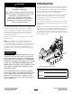
Form No. 3375-649 Rev A Z Master® Professional 6000 Series Riding Mower with 60in or 72in TURBO FORCE® Side Discharge Mower Model No. 74936—Serial No. 313000001 and Up Model No. 74938—Serial No. 313000001 and Up g019887 Register at www.Toro.com.
Introduction WARNING This rotary-blade, riding lawn mower is intended to be used by residential homeowners or professional, hired operators. It is designed primarily for cutting grass on well-maintained lawns on residential or commercial properties. It is not designed for cutting brush or for agricultural uses. CALIFORNIA Proposition 65 Warning This product contains a chemical or chemicals known to the State of California to cause cancer, birth defects, or reproductive harm.
Lubrication ...............................................................31 Greasing and Lubrication ........................................31 Where to Grease the Mower.....................................31 Lubricate Caster Wheel Hubs...................................32 Engine Maintenance ..................................................33 Servicing the Air Cleaner .........................................33 Servicing the Engine Oil..........................................
Operation Safety • Lightning can cause severe injury or death. If lightning Improper use or maintenance by the operator or owner can result in injury. To reduce the potential for injury, comply with these safety instructions and always pay attention to the safety alert symbol, which means CAUTION, WARNING, or DANGER-“personal safety instruction." Failure to comply with the instruction may result in personal injury or death.
Hauling • Extinguish all cigarettes, cigars, pipes, and other sources of ignition. • Use care when loading or unloading the machine into • Use only an approved fuel container. • Never remove fuel cap or add fuel with the engine or from a trailer or truck. • Use full width ramps for loading machine into trailer or running. truck. • Allow engine to cool before refueling. • Never refuel the machine indoors.
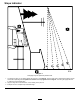
Slope Indicator G011841 Figure 3 This page may be copied for personal use. 1. The maximum slope you can safely operate the machine on is 15 degrees. Use the slope chart to determine the degree of slope of hills before operating. Do not operate this machine on a slope greater than 15 degrees. Fold along the appropriate line to match the recommended slope. 2. Align this edge with a vertical surface, a tree, building, fence pole, etc. 3. Example of how to compare slope with folded edge.
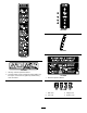
Safety and Instructional Decals Safety decals and instructions are easily visible to the operator and are located near any area of potential danger. Replace any decal that is damaged or lost. 68-8340 1-403005 98-5954 103-2076 54-9220 58-6520 1.
109-7232 110-2067 107-2102 107-3969 1. Warning—read the Operator's Manual. 2. Crushing hazard, mower—engage the parking brake, stop the engine, and remove the ignition key before working under the mower. 110-2068 1. Read the Operator's Manual. 114-4466 8 1. Main, 25A 3. Charge, 25A 2. PTO, 10A 4.
116-0205 115-7445 1. Grease pulleys and spindles 2. Maintenance interval—50 hours 116-0211 116-0090 116-0752 116-0157 1. Locked 9 2.
116-1654 116-4858 116-1716 1. Fuel 2. Empty 3. Half 4. Full 5. Battery 6. Hour meter 7. PTO 116-5944 8. Parking brake 9. Neutral 10. Operator presence switch 116-2643 Battery Symbols Some or all of these symbols are on your battery 1. Explosion hazard 6. Keep bystanders a safe distance from the battery. 2. No fire, open flame, or smoking. 7. Wear eye protection; explosive gases can cause blindness and other injuries 3. Caustic liquid/chemical burn hazard 4. Wear eye protection 8.
Manufacturer's Mark 1. Indicates the blade is identified as a part from the original machine manufacturer. 120-5897 1. Choke 2. Fast 4. Slow 5. Power take-off (PTO), Blade control switch 3.
Hour Meter Product Overview The hour meter records the number of hours the engine has operated. It operates when the engine is running. Use these times for scheduling regular maintenance (Figure 6). Fuel Gauge The fuel gauge is located with the hour meter and the bars light up when the ignition switch is on (Figure 6). The indicator light appears when the fuel level is low (approximately one gallon remaining in the fuel tank).
Blade Control Switch (PTO) Specifications The blade control switch (PTO) is used to engage the electric clutch and drive the mower blades. Pull the switch up to engage the blades and release. To disengage the blades, push the blade control switch (PTO) down or move a motion control lever into the neutral lock position. Note: Specifications and design are subject to change without notice. Width: Ignition Switch This switch is used to start the mower engine and has three positions: Start, Run and Off.
Operation DANGER In certain conditions during fueling, static electricity can be released causing a spark which can ignite the gasoline vapors. A fire or explosion from gasoline can burn you and others and can damage property. • Always place gasoline containers on the ground away from your vehicle before filling.
Filling the Fuel Tank Breaking In a New Machine Note: Do not fill the fuel tank completely full. Fill the fuel tank to the bottom of the filler neck. The empty space in the tank allows the gasoline to expand. New engines take time to develop full power. Mower decks and drive systems have higher friction when new, placing additional load on the engine. Allow 40 to 50 hours of break-in time for new machines to develop full power and best performance. 1. Park the machine on level ground. 2.
DANGER Operating on wet grass or steep slopes can cause sliding and loss of control. Wheels dropping over edges can cause rollovers, which may result in serious injury, death or drowning. There is no rollover protection when the roll bar is down. Always keep the roll bar in the fully raised and locked position and use the seat belt. Read and follow the rollover protection instructions and warnings. To avoid loss of control and possibility of rollover: • Do not operate near drop-offs or near water.
Operating the Mower Blade Control Switch (PTO) The use of protective equipment for eyes, ears, feet and head is recommended. 1 2 The blade control switch (PTO) starts and stops the mower blades and any powered attachments. Engaging the Blade Control Switch (PTO) G009027 Figure 10 1. Wear safety glasses Note: Engaging the blade control switch (PTO) with the throttle position at half or less will cause excessive wear to the drive belts. 2.
Operating the Throttle Important: Do not engage starter for more than 5 seconds at a time. If the engine fails to start allow a 15 second cool-down period between attempts. Failure to follow these instructions can burn out the starter motor. The throttle control can be moved between Fast and Slow positions (Figure 15). Always use the fast position when turning on the mower deck with the blade control switch (PTO).
Using the Fuel Shut-Off Valve The fuel shut-off valve is located under the seat. Move the seat forward to access it. Close the fuel shut-off valve for transport, maintenance, and storage. Ensure the fuel shut-off valve is open when starting the engine. 1 2 G008948 Figure 18 1. On g017006 Figure 19 2. Off 6. Turn the ignition key to the Start position (Figure 17). When the engines starts, release the key.
Stopping the Engine The Safety Interlock System CAUTION CAUTION Children or bystanders may be injured if they move or attempt to operate the machine while it is unattended. If safety interlock switches are disconnected or damaged the machine could operate unexpectedly causing personal injury. Always remove the ignition key and set the parking brake when leaving the machine unattended, even if just for a few minutes. • Do not tamper with the interlock switches.
Testing the Safety Interlock System Using the Motion Control Levers Service Interval: Before each use or daily Test the safety interlock system before you use the machine each time. If the safety system does not operate as described below, have an Authorized Service Dealer repair the safety system immediately. 1. Sitting on the seat, engage the parking brake and move the blade control switch (PTO) to on. Try starting the engine; the engine should not crank. 2.
Stopping the Machine To stop the machine, move the traction control levers to neutral and move to locked position, disengage the power take off (blade control switch (PTO), and turn the ignition key to off. Set the parking brake when you leave the machine; refer to Setting the Parking Brake in Operation. Remember to remove the key from the ignition switch. CAUTION Children or bystanders may be injured if they move or attempt to operate the machine while it is unattended.
Adjusting the Height-of-Cut Pin The height-of-cut is adjusted from 1 to 5-1/2 inches (25 to 140 mm) in 1/4 inch (6 mm) increments by relocating the clevis pin into different hole locations. 1. Move the transport lock to the lock position. 2. Push on the deck lift pedal with your foot and raise the mower deck to the transport position (also the 5-1/2 inch (140 mm) cutting height position) (Figure 27). 3. To adjust, rotate the pin 90 degrees and remove the pin from the height-of-cut bracket (Figure 27). 4.
Adjusting the Flow Baffle Cam Locks This procedure is applicable only to machines with the flow baffle locks. Certain models will have nuts and bolts in-place of the flow baffle locks and can be adjusted the same. The mower discharge flow can be adjusted for different types of mowing conditions. Position the cam locks and baffle to give the best quality of cut. 1. Disengage the blade control switch (PTO), move the motion control levers to the neutral locked position and set the parking brake. Figure 28 1.
Positioning the Flow Baffle • Use in tall, dense grass mowing conditions. The following figures are only recommendations for use. Adjustments will vary by grass type, moisture content, and height of grass. • Use in wet conditions. • Lowers the engine power consumption. • Allows increased ground speed in heavy conditions. Note: If the engine power draws down and the mower ground speed is the same, open up the baffle. • This position is similar to the benefits of the Toro SFS mower.
Positioning the Seat WARNING The seat can move forward and backward. Position the seat where you have the best control of the machine and are most comfortable. The engine and hydraulic drive units can become very hot. Touching a hot engine or hydraulic drive units can cause severe burns. To adjust, move the lever sideways to unlock seat (Figure 35). Allow the engine and hydraulic drive units to cool completely before accessing the drive wheel release valves.
Using the Side Discharge Loading Machines The mower has a hinged grass deflector that disperses clippings to the side and down toward the turf. Use extreme caution when loading units on trailers or trucks. One full width ramp that is wide enough to extend beyond the rear tires is recommended instead of individual ramps for each side of the unit (Figure 38). The lower rear section of the machine frame extends back between the rear wheels and serves as a stop for tipping backward.
Figure 39 1. Traction unit tie down loops Figure 38 1. Trailer 3. Not greater than 15 degrees 2. Full width ramp 4. Full width ramp—side view Transporting Machines Use a heavy-duty trailer or truck to transport the machine. Ensure that the trailer or truck has all necessary brakes, lighting, and marking as required by law. Please carefully read all the safety instructions. Knowing this information could help you, your family, pets or bystanders avoid injury.
Operating Tips cutting height higher than usual and cut the grass at this setting. Then cut the grass again using the lower, normal setting. Fast Throttle Setting When Stopping For best mowing and maximum air circulation, operate the engine at the fast throttle position. Air is required to thoroughly cut grass clippings, so do not set the height-of-cut so low as to totally surround the mower by uncut grass.
Maintenance Recommended Maintenance Schedule(s) Maintenance Service Interval Maintenance Procedure After the first 100 hours • Check the wheel lug nut torque. • Check the wheel hub slotted nut torque. • Check the park brake adjustment. After the first 250 hours • Change the hydraulic filters and hydraulic oil when using any type of oil. Before each use or daily • • • • • • • • Check the safety system. Check the engine oil level. Check the seat belt. Check the rollover protection system (ROPS) knobs.
CAUTION If you leave the key in the ignition switch, someone could accidently start the engine and seriously injure you or other bystanders. Remove the key from the ignition before you do any maintenance. Lubrication Where to Grease the Mower Greasing and Lubrication Service Interval: Every 50 hours—Grease the mower deck spindles and idler arm. Yearly—Grease the pump belt idler arm. Grease more frequently when operating conditions are extremely dusty or sandy.
Lubricate Caster Wheel Hubs Service Interval: Yearly 1. Stop the engine, wait for all moving parts to stop, and remove the key. Engage the parking brake. Figure 42 Figure 44 1. Seal guard 6. Remove the dust cap and adjust the caster pivots. Keep the dust cap off until greasing is done. Refer to Adjusting the Caster Pivot Bearing in Maintenance. 2. Spacer nut with wrench flats 2. Remove the caster wheel from the caster forks. 7. Remove the hex plug. Thread a grease zerk into the hole. 3.
14. Engine Maintenance Reinstall the seal guards over the wheel hub and insert wheel into caster fork. Reinstall caster bolt and tighten nut fully. WARNING Important: To prevent seal and bearing damage, check the bearing adjustment often. Spin the caster tire. The tire should not spin freely (more than 1 or 2 revolutions) or have any side play. If the wheel spins freely, adjust torque on spacer nut until there is a slight amount of drag. Reapply thread locking adhesive.
1 3 2 Figure 45 1. Air cleaner body 4. Air cleaner latch 2. Inner air filter 3. Primary air filter 5. Air cleaner cover G016165 Figure 46 1. Air cleaner cover 2. Throttle mechanism Servicing the Primary Filter 3. Breathe valve. • If the primary filter is dirty, bent, or damaged, replace it. 5. Secure the cover with the latches (Figure 45). • Do not clean the primary filter. Servicing the Inner Filter Servicing the Engine Oil Replace the inner filter, never clean it.
Checking the Engine Oil Level Service Interval: Before each use or daily Note: Check the oil when the engine is cold. WARNING G008804 Contact with hot surfaces may cause personal injury. 1 2 3 4 6 7 8 9 Keep hands, feet, face, clothing and other body parts away from the muffler and other hot surfaces. Important: Do not overfill the crankcase with oil because damage to the engine may result. Do not run engine with oil below the low mark because the engine may be damaged. 5 1.
Changing the Engine Oil 5. Slowly pour approximately 80% of the specified oil into the filler tube and slowly add the additional oil to bring it to the Full mark (Figure 50). Service Interval: Every 150 hours (more often in dirty or dusty conditions) Note: Dispose of the used oil at a recycling center. 1 2 3 4 5 6 1. Start the engine and let it run five minutes. This warms the oil so it drains better. 2.
Servicing the Spark Plug Service Interval: Every 200 hours—Check, clean and regap the spark plug. Every 600 hours—Replace the spark plugs. Make sure the air gap between the center and side electrodes is correct before installing the spark plug. Use a spark plug wrench for removing and installing the spark plug(s) and a gapping tool/feeler gauge to check and adjust the air gap. Install a new spark plug(s) if necessary. G015196 1 2 Type : Champion® XC10YC or equivalent Air Gap: 0.030 inch (0.
Checking the Spark Plug Important: Replace the spark plug(s) when it has: a black coating, worn electrodes, an oily film, cracks or reuse is questionable. If you see light brown or gray on the insulator, the engine is operating properly. A black coating on the insulator usually means the air cleaner is dirty. Set the gap to 0.030 inches (0.76 mm). 1 2 G008794 Figure 54 Installing the Spark Plug Tighten the spark plug(s) to 18-22 ft.-lb (24.4–29.8 N-m). 1 Figure 52 1.
Check Spark Arrester (if equipped) Fuel System Maintenance Service Interval: Every 50 hours Replacing the Fuel Filter WARNING Service Interval: Every 150 hours/Yearly (whichever comes first) (more often in dirty or dusty conditions). Hot exhaust system components may ignite gasoline vapors even after the engine is stopped. Hot particles exhausted during engine operation may ignite flammable materials. Fire may result in personal injury or property damage.
Servicing the Fuel Tank Electrical System Maintenance Do not attempt to drain the fuel tank. Ensure that an Authorized Service Dealer drains the fuel tank and services any components of the fuel system. Servicing the Battery Service Interval: Monthly WARNING CALIFORNIA Proposition 65 Warning Battery posts, terminals, and related accessories contain lead and lead compounds, chemicals known to the State of California to cause cancer and reproductive harm. Wash hands after handling.
WARNING Incorrect battery cable routing could damage the machine and cables causing sparks. Sparks can cause the battery gasses to explode, resulting in personal injury. G008804 • Always Disconnect the negative (black) battery cable before disconnecting the positive (red) cable. 1 2 3 4 - 1. Disengage the blade control switch (PTO), move the motion control levers to the neutral locked position and set the parking brake.
Charging the Battery Servicing the Fuses The electrical system is protected by fuses. It requires no maintenance, however, if a fuse blows check the component/circuit for a malfunction or short. WARNING Charging the battery produces gasses that can explode. 1. The fuses are located on right hand console next to the seat (Figure 59). Never smoke near the battery and keep sparks and flames away from battery. 2. To replace the fuses, pull out on the fuse to remove it. 3. Install a new fuse (Figure 59).
Drive System Maintenance Checking the Seat Belt Service Interval: Before each use or daily Visually inspect seat belt for wear, cuts, and proper operation of retractor and buckle. Replace before operating if damaged. Checking the Rollover Protection System (ROPS) Knobs Service Interval: Before each use or daily Check that both the mounting hardware and the knobs are in good working condition. Make sure the knobs are fully engaged with the ROPS in the fully raised position.
Checking the Wheel Lug Nuts Check and torque the wheel lug nuts to 90-95 ft-lb (122-129 N-m). Checking the Wheel Hub Slotted Nut Service Interval: After the first 100 hours Every 500 hours See Figure 63 to determine which slotted nut has been installed on the unit. Figure 63 g019756 Figure 61 Left control lever shown 1. Control lever 1. Style A (black finish) 3. Style B (yellow zinc) 2. .03 inch (.76 mm) 4. .24 inch (6 mm) • Style A (black finish): 3.
Using the Clutch Shim 6. Then tighten nut until the next set of slots line up with the cross hole in shaft. Do not loosen nut to align the slot. If required, tighten to the next set of slots. Some later model year units have been built with clutches that contain a brake shim. When the clutch brake has worn to the point where the clutch no longer engages consistently, the shim can be removed to extend the clutch life. 7. Install a new cotter pin. Note: Do Not use anti-seize on wheel hub.
A. Loosen both brake mounting bolts one-half to one full turn as shown below. Note: Do Not remove the brake pole from the field shell/armature. The brake pole has worn to match the armature and needs to continue to match after the shim is removed to ensure proper brake torque. Figure 70 1. Feeler gauge Figure 68 1. Brake mounting bolt Figure 71 B. Using needle nose pliers, or by hand, take hold of the tab and remove the shim (Do Not discard the shim until proper clutch function has been confirmed). 1.
Cleaning the Engine Screen Cooling System Maintenance Service Interval: Before each use or daily Before each use remove any build-up of grass, dirt or other debris from the engine screen. This will help insure adequate cooling and correct engine speed and will reduce the possibility of overheating and mechanical damage to the engine. Servicing the Engine Oil Cooler Service Interval: Every 150 hours Cleaning the Engine Cooling Fins and Shrouds 1.
3 2 1 2 4 4 g016907 Figure 74 1. Oil filter 3. Battery 2. Left side bolts for cooling fan housing 4. Right side bolts for cooling fan housing 7. Remove the cooling fan housing. Figure 75 8. Using compressed air, blow out any debris and grass from the engine parts, particularly around the cylinder head cooling fins and ignition coils. 1. Hydraulic unit shrouds 9. Install all the shrouds on to the engine. Check and Clean the Hydraulic Unit Shrouds Service Interval: Before each use or daily 1.
Brake Maintenance Adjusting the Parking Brake Service Interval: After the first 100 hours Every 500 hours thereafter Check to make sure brake is adjusted properly. This procedure must be followed after the first 100 hours or when a brake component has been removed or replaced. 1. Drive the machine onto a level surface. 2. Disengage the blade control switch (PTO), move the motion control levers to the neutral locked position and set the parking brake. Figure 76 Left Hand Brake Shown 3.
Belt Maintenance Inspecting the Belts Service Interval: Every 50 hours Check the belts for squealing when the belt is rotating, blades slipping when cutting grass, frayed belt edges, burn marks and cracks are signs of a worn mower belt. Replace the mower belt if any of these conditions are evident. Replacing the Mower Belt Squealing when the belt is rotating, blades slipping when cutting grass, frayed belt edges, burn marks and cracks are signs of a worn mower belt.
Figure 79 1. Position the belt cover 3. Ensure the tab is under the metal catch Figure 80 2. Slide belt cover under the side catches 1. Idler pulley 5. Left hand hydraulic pump pulley 2. Clutch pulley 6. Square hole in idler arm 3. Pump drive belt 7. Idler spring 4. Right hand hydraulic pump pulley Replacing the Hydraulic Pump Drive Belt 5. Use a ratchet in the square hole in the idler arm to remove the idler spring (Figure 80). 1. Disengage the PTO and set the parking brake. 2.
Controls System Maintenance Adjusting the Control Handle Position There are two height positions for the control levers; high and low. Remove the bolts to adjust the height for the operator. 1. Disengage the PTO, move the motion control levers to the neutral locked position, and set the parking brake. 2. Stop the engine, remove the key, and wait for all moving parts to stop before leaving the operating position. 3. Loosen the bolts and flange nuts installed in the levers (Figure 81). 4.
6. Run the unit at least 5 minutes with the drive levers at full forward speed to bring hydraulic oil up to operating temperature. Note: The motion control lever needs to be in neutral while making any necessary adjustments. 7. Bring the motion control levers into the neutral position. Adjust pump control rod lengths by rotating the double nuts on the rod in the appropriate direction until the wheels slightly creep in reverse (Figure 83).
Hydraulic System Maintenance Servicing the Hydraulic System Hydraulic Oil Type: Toro® HYPR-OIL™ 500 hydraulic oil or Mobil® 1 15W-50. 3 H Important: Use oil specified. Other fluids could cause system damage. Each Hydraulic System Oil Capacity: 52 ounces (1.5 l) per side with filter change Checking the Hydraulic Oil Service Interval: Every 50 hours—Check the hydraulic oil level. 1. Position the machine on a level surface. 2.
Replacing the Hydraulic Filters and Hydraulic Oil 1 Service Interval: After the first 250 hours—Change the hydraulic filters and hydraulic oil when using any type of oil. Every 250 hours—Change the hydraulic filters and hydraulic oil when using Mobil® 1 oil (more often in dirty or dusty conditions). Every 500 hours—Change the hydraulic filters and hydraulic oil when using Toro® HYPR-OIL™ 500 hydraulic oil (more often in dirty or dusty conditions).
Mower Deck Maintenance 3 1 Leveling the Mower Deck Setting Up the Machine Note: Ensure the mower deck is leveled before matching the height-of-cut (HOC). 2 1. Position mower on a flat surface. 2. Disengage the blade control switch (PTO), move the motion control levers to the neutral locked position and set the parking brake. 3. Stop the engine, remove the key, and wait for all moving parts to stop before leaving the operating position. G017027 4. Check tire pressure of the drive tires.
10. Fine-tune the adjustment nut on the front deck lift assembly by turning it (Figure 91). To increase the height, turn the adjustment nut clockwise; to decrease, turn counterclockwise. 3 4 2 1 2 1 1 g017029 Figure 92 1. Bolts at the bottom of the height-of-cut plate 13. If the deck is too low, tighten the single point adjustment bolt by rotating it clockwise. If the deck is too high, loosen the single point adjustment bolt by rotating it counterclockwise (Figure 93). G012430 Figure 91 1.
Servicing the Cutting Blades 15. On both sides of the deck, measure from the level surface to the back tip of the blade (Postion B). The measurement should read 3 1/4 inches (8.3 cm) (Figure 90). Maintain sharp blades throughout the cutting season because sharp blades cut cleanly without tearing or shredding the grass blades. Tearing and shredding turns grass brown at the edges, which slows growth and increases the chance of disease. 16.
Checking for Bent Blades by other manufacturers may result in non-conformance with safety standards. 1. Disengage the blade control switch (PTO), move the motion control levers to the neutral locked position and set the parking brake. 1. Hold the blade end using a rag or thickly-padded glove. 2. Remove the blade bolt, curved washer, and blade from the spindle shaft (Figure 96). 2. Stop the engine, remove the key, and wait for all moving parts to stop before leaving the operating position. 3.
Removing the Mower Deck the sail area only (Figure 99). Repeat this procedure until the blade is balanced. Before servicing or removing the mower deck, the spring loaded deck arms must be locked out. WARNING Deck lift arm assemblies have stored energy. Removing the deck with out releasing the stored energy can cause serious injury or death. Figure 98 1. Blade 2. Balancer Do Not attempt to disassemble the deck from the front frame without locking out the stored energy. Installing the Blades 1.
Figure 101 1. Right stabilizer Figure 100 1. Clutch pulley 2. Mower belt 5. Square hole in the idler arm for the ratchet 6. Idler grease zerk 3. Spring loaded idler pulley 7. Belt guide 2. Deck strut (right side shown) 3. Remove the rear deck lift attachment shoulder bolt and nut. 4. Remove the front deck lift attachment shoulder bolt and nut. 8. Raise the deck struts and secure them in the up position. Slide the deck out to the right side of the machine. 4. Ratchet 7.
6 2 4 Cleaning 7 Cleaning Under the Mower 3 Service Interval: Before each use or daily 1. Disengage the blade control switch (PTO), move the motion control levers to the neutral locked position and set the parking brake. 1 2. Stop the engine, remove the key, and wait for all moving parts to stop before leaving the operating position. 5 3. Raise the mower to the transport position. g015594 Figure 102 1. Bolt Waste Disposal 5. Spring installed 2. Spacer 6. Grass Deflector 3. Locknut 7.
Storage Cleaning and Storage 1. Disengage the power take off (blade control switch (PTO), set the parking brake, and turn the ignition key to Off. Remove the key. Stop the engine, allow it to cool, and drain the fuel tank; refer to Servicing the Fuel Tank in the Maintenance Section. D. Restart the engine and run it until it stops. E. Dispose of fuel properly. Recycle as per local codes. Important: Do not store stabilizer/conditioned fuel over 90 days. 2.
Troubleshooting Problem Starter does not crank Engine will not start, starts hard, or fails to keep running Possible Cause 1. Blade control switch (PTO) is engaged. 1. Move blade control switch (PTO) to disengaged. 2. Parking brake is not on. 3. Drive levers are not in neutral lock position. 4. Operator is not seated. 5. Battery is dead. 6. Electrical connections are corroded or loose. 7. Fuse is blown. 8. Relay or switch is defective. 2. Set the parking brake. 3.
Problem Machine does not drive. Abnormal vibration. Uneven cutting height. Possible Cause 1. By pass valves is not closed tight. 1. Tighten the by pass valves. 2. 3. 4. 5. 2. 3. 4. 5. Pump belt is worn, loose or broken. Pump belt is off a pulley. Broken or missing idler spring. Hydraulic oil level is low or too hot. 1. Install new cutting blade(s). 2. Blade mounting bolt is loose. 3. Engine mounting bolts are loose. 4. Loose engine pulley, idler pulley, or blade pulley. 5. Engine pulley is damaged.
Schematics Wire Diagram (Rev.
Notes: 67
The Toro Total Coverage Warranty Landscape Contractor Equipment (LCE) A Limited Warranty (see warranty periods below) Conditions and Products Covered This warranty includes the cost of parts and labor, but you must pay transportation costs. The Toro Company and its affiliate, Toro Warranty Company, pursuant to an agreement between them, jointly promise to the original purchaser to repair the Toro Products listed below if defective in materials or workmanship.