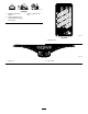
Form No. 3442-165 Rev A Titan® MR 4800, MR 5400, or MR 6000 Riding Mower Model No. 75316TA—Serial No. 400000000 and Up Model No. 75317TA—Serial No. 400000000 and Up Model No. 75318TA—Serial No. 400000000 and Up Register at www.Toro.com.
Gross or Net Torque: The gross or net torque of this engine was laboratory rated by the engine manufacturer in accordance with the Society of Automotive Engineers (SAE) J1940 or J2723. As configured to meet safety, emission, and operating requirements, the actual engine torque on this class of mower will be significantly lower. Please refer to the engine manufacturer’s information included with the machine. Go to www.Toro.com to view specifications on your model. g297254 Figure 1 Introduction 1.
Contents Checking the Tire Pressure............................... 38 Belt Maintenance ................................................ 38 Inspecting the Belts .......................................... 38 Replacing the Mower Belt ................................. 38 Mower Maintenance............................................. 40 Blade Safety ..................................................... 40 Servicing the Cutting Blades ............................. 40 Leveling the Mower Deck......................
Safety This machine has been designed in accordance with ANSI standard B71.1-2017. General Safety This product is capable of amputating hands and feet and of throwing objects. Always follow all safety instructions to avoid serious personal injury or death. • Read and understand the contents of this Operator’s Manual before starting the engine. • Keep bystanders and children away. • Do not allow children or untrained people to operate or service the machine.
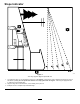
Slope Indicator g011841 Figure 3 You may copy this page for personal use. 1. The maximum slope you can operate the machine on is 15 degrees. Use the slope chart to determine the degree of slope of hills before operating. Do not operate this machine on a slope greater than 15 degrees. Fold along the appropriate line to match the recommended slope. 2. Align this edge with a vertical surface, a tree, building, fence pole, etc. 3.
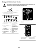
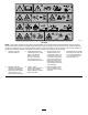
Safety and Instructional Decals Safety decals and instructions are easily visible to the operator and are located near any area of potential danger. Replace any decal that is damaged or missing. decaloemmarkt Manufacturer's Mark 1. This mark indicates that the blade is identified as a part from the original machine manufacturer. decal117-1194 117-1194 decalbatterysymbols Battery Symbols Some or all of these symbols are on your battery. 1. Explosion hazard 6. Keep bystanders away from the battery. 2.
decal130-0731 130-0731 1. Warning—thrown object hazard; keep the deflector shield in place. 2. Cutting hazard of hand or foot, mower blade—keep away from moving parts. decal136-4243 136-4243 1. Fast 2. Slow 4. Reverse 5. Parking brake disengaged 3. Neutral 6. Parking brake engaged decal130-0765 130-0765 1. Read the Operator's Manual. 3. Remove the key before performing maintenance. decal136-4244 136-4244 2. Height-of-cut selection 1. Fast 2. Slow 3. Neutral 4.
decal138-2456 138-2456 1. Read the Operator’s Manual. 2. Park the machine on a level surface when filling the fuel tank. 3. Do not overfill the fuel tank. decal139-3550 139-3550 1. Height of cut decal133-5198 133-5198 1. Cam lock 2.
decal132-0869 132-0869 Note: This machine complies with the industry standard stability test in the static lateral and longitudinal tests with the maximum recommended slope indicated on the decal. Review the instructions for operating the machine on slopes in the Operator’s Manual as well as the conditions in which you would operate the machine to determine whether you can operate the machine in the conditions on that day and at that site.
decal139-7473 139-7473 1. Fast 4. PTO—disengage 2. Slow 5. PTO—engage 3.
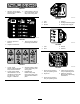
Product Overview g335518 Figure 4 1. Deck-lift pedal 4. Controls 7. Fuel cap 10. Caster wheel 11. Parking-brake lever 2. Height-of-cut pin 5. Engine 8. Mower deck 3. Motion-control lever 6. MyRide™ suspension system 9.
Controls Choke Control Become familiar with all the controls before you start the engine and operate the machine. Use the choke control to start a cold engine (Figure 5). Hour Meter Control Panel The hour meter records the number of hours the engine has operated. It operates when the engine is running. Use these times for scheduling regular maintenance (Figure 5). Motion-Control Levers Use the motion-control levers to drive the machine forward, reverse, and turn either direction (Figure 4).
Height-of-Cut Pin Operation The height-of-cut pin works with the foot pedal to lock the deck in a specific cutting height. Adjust the height of cut only when the machine is not moving (Figure 4). Note: Determine the left and right sides of the machine from the normal operating position. Attachments/Accessories Before Operation A selection of Toro approved attachments and accessories is available for use with the machine to enhance and expand its capabilities.
Fuel Safety compartment to help prevent fires. Clean up oil or fuel spills. • Fuel is extremely flammable and highly explosive. A fire or explosion from fuel can burn you and others and can damage property. Adding Fuel – To prevent a static charge from igniting the fuel, place the container and/or machine directly on the ground before filling, not in a vehicle or on an object. Recommended Fuel – Fill the fuel tank outdoors on level ground, in an open area, and when the engine is cold.
Using the Safety-Interlock System WARNING If the safety-interlock switches are disconnected or damaged, the machine could operate unexpectedly, causing personal injury. • Do not tamper with the interlock switches. • Check the operation of the interlock switches daily and replace any damaged switches before operating the machine. Understanding the Safety-Interlock System The safety-interlock system is designed to prevent the engine from starting unless: • The blade-control switch (PTO) is disengaged.
4. 5. Adjusting the MyRide™ Suspension System Sit on the seat, engage the parking brake, move the blade-control switch (PTO) to the OFF position, and move the motion-control levers to NEUTRAL-LOCK position. Start the engine. While the engine is running, center either motion-control lever and move it forward or reverse; the engine should shut off. Repeat for other motion-control lever. The MyRide™ suspension system adjusts to provide a smooth and comfortable ride.
Adjusting the Motion-Control Levers Adjusting the Height You can adjust the motion-control levers higher or lower for maximum comfort (Figure 11). g335104 g333847 Figure 11 Adjusting the Tilt You can adjust the motion-control levers forward or rearward for your comfort. 1. Loosen the upper bolt holding the control lever to the control-arm shaft. 2. Loosen the lower bolt just enough to pivot the control lever forward or rearward. g195745 Figure 10 g333846 Figure 12 17 3.
During Operation – Engage the parking brake. – Shut off the engine and remove the key. – Wait for all moving parts to stop. During Operation Safety • Operate the engine only in well-ventilated areas. Exhaust gases contain carbon monoxide, which is lethal if inhaled. General Safety • Never leave a running machine unattended. • Attach towed equipment to the machine only at • The owner/operator can prevent and is responsible for accidents that may cause personal injury or property damage.
• Before backing up or turning the machine, look • These can change the stability of the machine and cause a loss of control. Follow directions for counterweights. down and all around for small children. Do not carry children on the machine, even when the blades are not moving. Children could fall off and be seriously injured or prevent you from safely operating the machine.
Entering the Operator’s Position Use the mower deck as a step to get into the operator’s position (Figure 15). g188777 Figure 17 1. Push the parking brake out of the detent slot and toward you. 2. Push the parking brake down. Engaging the Blade-Control Switch (PTO) g029797 Figure 15 1. Step here. Operating the Parking Brake Always engage the parking brake when you stop the machine or leave it unattended.
Disengaging the Blade-Control Switch (PTO) g009174 Figure 20 Operating the Throttle g295540 Figure 22 You can move the throttle control between the FAST and SLOW positions (Figure 21). 1. ON position 2. OFF position Always use the FAST position when engaging the PTO. Operating the Key Switch 1. Turn the key to the START position (Figure 23). Note: When the engine starts, release the key. Important: Do not engage the starter motor for more than 5 seconds at a time.
Starting the Engine CAUTION Children or bystanders may be injured if they move or attempt to operate the machine while it is unattended. Note: A warm or hot engine may not require choking. Important: Do not engage the starter for more than 5 seconds at a time. Engaging the starter motor for more than 5 seconds can damage the starter motor. If the engine fails to start, wait 10 seconds before operating the engine starter again.
Driving the Machine The drive wheels turn independently, powered by hydraulic motors on each axle. You can turn 1 side in reverse while you turn the other forward, causing the machine to spin rather than turn. This greatly improves the machine maneuverability but may require some time for you to adapt to how it moves. The throttle control regulates the engine speed as measured in rpm (revolutions per minute). Place the throttle control in the FAST position for best performance.
Using the Side Discharge Adjusting the Height of Cut The mower has a hinged grass deflector that disperses clippings to the side and down toward the turf. The machine is equipped with a foot pedal deck-lift system. You can use the foot pedal to lift the deck briefly to avoid obstacles and to raise the deck. You can adjust the height of cut from 38 to 114 mm (1-1/2 to 4-1/2 inches) in 6 mm (1/4 inch) increments by moving the height-of-cut pin into different hole locations.
2. 3. Alternating the Mowing Direction Shut off the engine, remove the key, and wait for all moving parts to stop before leaving the operating position. Alternate the mowing direction to keep the grass standing straight. This also helps disperse clippings, which enhances decomposition and fertilization. Adjust the anti-scalp rollers as shown in Figure 29. Mowing at Correct Intervals Grass grows at different rates at different times of the year.
Pushing the Machine by Hand After Operation After Operation Safety Important: Always push the machine by hand. Do not tow the machine, because towing may damage it. General Safety • Shut off the engine, remove the key, and wait Pushing the Machine for all moving parts to stop before leaving the operator’s position. Allow the machine to cool before servicing, adjusting, fueling, cleaning, or storing it.
Transporting the Machine Use a heavy-duty trailer or truck to transport the machine. Use a full-width ramp. Ensure that the trailer or truck has all the necessary brakes, lighting, and marking as required by law. Please carefully read all the safety instructions. Knowing this information could help you or bystanders avoid injury. Refer to your local ordinances for trailer and tie-down requirements.
1. If using a trailer, connect it to the towing vehicle and connect the safety chains. 2. If applicable, connect the trailer brakes and lights. 3. Lower the ramp, ensuring that the angle between the ramp and the ground does not exceed 15 degrees (Figure 31). 4. Back the machine up the ramp (Figure 32). g027995 Figure 32 1. Back the machine up the ramp. 2. Drive the machine forward down the ramp. 5. Shut off the engine, remove the key, and engage the parking brake. 6.
Maintenance Note: Determine the left and right sides of the machine from the normal operating position. Maintenance Safety • If you leave the key in the switch, someone could accidently start the engine and seriously injure you or other bystanders. Remove the key from the switch before you perform any maintenance. • Before you leave the operator’s position, do the following: – Park the machine on a level surface. – Disengage the drives. – Engage the parking brake. – Shut off the engine and remove the key.
Recommended Maintenance Schedule(s) Maintenance Service Interval Maintenance Procedure After the first 8 hours • Change the engine oil. Before each use or daily • • • • • • Check the safety-interlock system. Clean and check the air-cleaner element. Check the engine-oil level. Clean the air intake screen. Inspect the blades. Inspect the grass deflector for damage. Every 25 hours • Check tire pressure. • Check the belts for wear or cracks.
Engine Maintenance Servicing the Paper Air-Cleaner Element Engine Safety Service Interval: Every 100 hours—Clean the paper air-cleaner element (more often in dirty or dusty conditions). • Keep your hands, feet, face, clothing, and other body parts away from the muffler and other hot surfaces. Allow engine components to cool before performing maintenance. Do not change the engine governor speed or overspeed the engine.
Checking the Engine-Oil Level Changing the Engine Oil Service Interval: Before each use or daily Service Interval: After the first 8 hours—Change the engine oil. Note: Check the oil when the engine is cold. Every 100 hours—Change the engine oil (more often in dirty or dusty conditions). Important: If you overfill or underfill the engine crankcase with oil and run the engine, you may damage the engine. 1. 2. 3. 1.
g235264 Figure 38 6. Dispose of the used oil at a recycling center. g027477 Figure 39 Changing the Engine-Oil Filter Service Interval: Every 200 hours—Change the engine-oil filter (more often in dirty or dusty conditions). 1. Drain the oil from the engine; refer to Changing the Engine Oil (page 32). 2. Change the engine-oil filter (Figure 39). Note: Ensure that the oil-filter gasket touches the engine, and then turn the oil filter an extra 3/4 turn. 3.
2. Shut off the engine, remove the key, and wait for all moving parts to stop before leaving the operating position. 3. Clean the area around the base of the plug to keep dirt and debris out of the engine. 4. Remove the spark plug (Figure 40). Installing the Spark Plug g027478 Figure 40 g028109 Figure 42 Checking the Spark Plug Important: Do not clean the spark plug(s). Always replace the spark plug(s) when it has a black coating, worn electrodes, an oily film, or cracks.
Fuel System Maintenance DANGER g027590 In certain conditions, fuel is extremely flammable and highly explosive. A fire or explosion from fuel can burn you and others and can damage property. Refer to Fuel Safety (page 14) for a complete list of fuel related precautions. Replacing the In-Line Fuel Filter Service Interval: Every 100 hours—Replace the in-line fuel filter. Never install a dirty filter after removing it from the fuel line. 1.
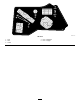
Electrical System Maintenance Electrical System Safety • Disconnect the battery before repairing the machine. Disconnect the negative terminal first and the positive last. Connect the positive terminal first and the negative last. • Charge the battery in an open, well-ventilated g297596 area, away from sparks and flames. Unplug the charger before connecting or disconnecting the battery. Wear protective clothing and use insulated tools. Figure 44 1. Battery cover 4. Servicing the Battery 2.
Charging the Battery Servicing the Fuses Service Interval: Before storage—Charge the battery and disconnect the battery cables. The electrical system is protected by fuses. It requires no maintenance; however, if a fuse blows, check the component/circuit for a malfunction or short. 1. 2. Remove the battery from the chassis; refer to Removing the Battery (page 36). Fuse type: Charge the battery for a minimum of 1 hour at 6 to 10 A.
Drive System Maintenance Belt Maintenance Checking the Tire Pressure Service Interval: Every 25 hours—Check the belts for wear or cracks. Inspecting the Belts Service Interval: Every 25 hours—Check tire pressure. Replace the belt if it is worn. The signs of a worn belt include squealing while the belt is rotating; the blades slipping while cutting grass; and frayed edges, burn marks, and cracks on the belt. Maintain the air pressure in the front and rear tires as specified.
7. Route the new belt around the engine pulley and mower pulleys (Figure 52). 8. Using a spring-removal tool (Toro Part No. 92-5771), install the idler spring over the deck hook and place tension on the idler pulley and the mower belt (Figure 52). 9. Tighten the nut securing the wire form to the idler pulley (Figure 51). Note: Position the wire form against the idler arm as shown in Figure 51. 10. g334161 Figure 51 3. Idler pulley 1. Wire form 2. Nut 6. Using a spring-removal tool (Toro Part No.
Mower Maintenance Blade Safety • Inspect the blades periodically for wear or damage. • Use care when checking the blades. Wrap the blades or wear gloves, and use caution when servicing the blades. Only replace or sharpen the blades; never straighten or weld them. g006530 Figure 53 • On multi-bladed machines, take care as rotating one blade can cause other blades to rotate. 1. Cutting edge 3. Wear/slot forming 2. Curved area 4.
g014973 g014973 Figure 55 Figure 57 1. Blade (in position for measuring) 1. Opposite blade edge (in position for measuring) 2. Level surface 3. Measured distance between blade and the surface (A) 2. Level surface 3. Second measured distance between blade and surface (B) 4. Rotate the same blade 180 degrees so that the opposing cutting edge is now in the same position (Figure 56). A.
Removing the Blades Replace the blades if they hit a solid object, or if the blade is out of balance or bent. 1. Hold the blade end using a rag or thickly padded glove. 2. Remove the blade bolt, curved washer, and blade from the spindle shaft (Figure 58). g000553 Figure 60 1. Blade 3. 2. Balancer Repeat this procedure until the blade is balanced. Installing the Blades 1. Install the blade onto the spindle shaft (Figure 58).
Leveling the Mower Deck Checking the Front-to-Rear Blade Slope Check to ensure that the mower deck is level any time you install the mower or when you see an uneven cut on your lawn. Check the front-to-rear blade level any time you install the mower. If the front of the mower is more than 7.9 mm (5/16 inch) lower than the rear of the mower, adjust the blade level.
Leveling the Mower Deck 1. Set the anti-scalp rollers to the top holes or remove them completely for this procedure; refer to Adjusting the Anti-Scalp Rollers (page 24). 2. Set the height-of-cut lever to the 76 mm (3 inch) position; refer to Adjusting the Height of Cut (page 24). 3. Place 2 blocks, each having a thickness of 6.6 cm (2-5/8 inches), under each side of the front edge of the deck but not under the anti-scalp roller brackets (Figure 64). 4. Place 2 blocks, each having a thickness of 7.
Removing the Mower Deck 1. Park the machine on a level surface, disengage the blade-control switch (PTO), and engage the parking brake. 2. Shut off the engine, remove the key, and disconnect the spark-plug wires from the spark plugs. 3. Lower the mower to the 76 mm (3 inches) height-of-cut position. 4. Remove the mower belt from the engine pulley; refer to Replacing the Mower Belt (page 38). 5.
Replacing the Grass Deflector 3. Position the new discharge deflector with the bracket ends between the welded brackets on the deck as shown in Figure 69. Service Interval: Before each use or daily—Inspect the grass deflector for damage. 4. Install the spring onto the straight end of the rod. 5. Position the spring on the rod as shown in Figure 69 so that the shorter spring end comes from under the rod before the bend and going over the rod as it returns from the bend. 6.
Cleaning Storage Cleaning the Suspension System Storage Safety • Shut off the engine, remove the key, and wait for all moving parts to stop before you leave the operator’s position. Allow the machine to cool before adjusting, servicing, cleaning, or storing it. Do not store the machine or fuel near flames or drain the fuel indoors or inside an enclosed trailer. Do not store the machine or fuel container where there is an open flame, spark, or pilot light, such as on a water heater or on other appliances.
A. Storing the Battery Add fuel stabilizer/conditioner to fresh fuel in the tank. Follow mixing instructions from the fuel stabilizer manufacturer. Do not use an alcohol-based stabilizer (ethanol or methanol). B. Run the engine to distribute conditioned fuel through the fuel system for 5 minutes. C. Shut off the engine, allow it to cool, and drain the fuel tank. D. Start the engine and run it until it shuts off. E. Dispose of fuel properly. Recycle the fuel according to local codes. 1.
Troubleshooting Problem Possible Cause The fuel tank is showing signs of collapsing or the machine is frequently showing signs of running out of fuel. 1. The air-cleaner paper element clogged. The engine overheats. 1. The engine load is excessive. 1. Reduce the ground speed. 2. The oil level in the crankcase is low. 3. The cooling fins and air passages under the engine-blower housing are plugged. 4. The air cleaner is dirty. 2. Add oil to the crankcase. 3.
Problem The machine does not drive. The machine vibrates abnormally. The cutting height is uneven. The blades do not rotate. Possible Cause Corrective Action 1. The bypass valves are open. 1. Close the tow valves. 2. The traction belts are worn, loose, or broken. 3. The traction belts are off the pulleys. 4. The transmission has failed. 2. Contact an Authorized Service Dealer. 1. The cutting blade(s) is/are bent or unbalanced. 1. Install new cutting blade(s). 2. The blade mounting bolt is loose.
Schematics g297640 Electrical Diagram (Rev.