
Operator's Manual

A.Raisethedecktothetransportposition
(12.7cmor5inches).
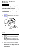
B.Slowlyloosentheadjustingscrewonthe
lift-assistspringuntilyoucanremovethe
screw(seeFigure95).
Note:Savethescrewforinstallation.
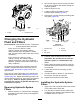
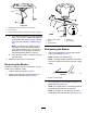
g035850
Figure95
Reardischargemowerdeckshown
1.Adjustingscrew
3.Setthegapto22to29
mm(7/8to1-1/8inch).
2.Bracket
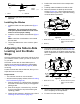
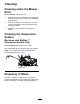
10.Place2blocks(seeBlockHeightandRake
Table)undertherearedgeofthecuttingdeck
skirt;1oneachsideofthecuttingdeck(Figure
96).
11.Settheheight-of-cutlevertothe3inch(76mm)
position.
12.Place2blocksundereachsideofthefrontedge
ofthedeck,butnotundertheanti-scalproller
bracketsorwelds.
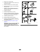
g038090
Figure96
Bottomview
1.Block—7.3cm(2.87
inches)
2.Welds
BlockHeightandRakeTable
Deck
Size
FrontBlockHeightRake
Allmower
decks
7.3cm(2.87inches)4.8to6.4mm(3/16to1/4
inch)
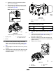
13.Carefullyrotatethebladessidetoside(Figure
93).
14.Loosenthelocknuts(Figure97)onall4corners
andensurethatthemowerdeckissitting
securelyonall4blocks.
15.Removeanyslackfromthedeckhangersand
makesurethedeck-liftfootleverispushedback
againstthestop.
16.Tightenthe4locknuts.
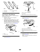
g035851
Figure97
1.Locknuts3.Deckhanger
2.Deckliftarm4.Chain
67