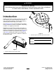
Form No. 3450-666 Rev A 60in or 72in E-Z Vac™ DFS Collection System Z Master® 4000 Series Riding Mower Model No. 78468—Serial No. 400000000 and Up Model No. 78474—Serial No. 400000000 and Up Register at www.Toro.com.
WARNING CALIFORNIA Proposition 65 Warning Use of this product may cause exposure to chemicals known to the State of California to cause cancer, birth defects, or other reproductive harm. Introduction Read this information carefully to learn how to operate and maintain your product properly and to avoid injury and product damage. You are responsible for operating the product properly and safely. Visit www.Toro.
Removing the Bagger ....................................... 33 Using the Grass Deflector................................. 34 Transporting Machines ..................................... 34 Maintenance ........................................................... 35 Recommended Maintenance Schedule(s) ........... 35 Cleaning the Bagger Screen ............................. 35 Cleaning the Collection System ........................ 35 Inspecting the Blower Belt ................................
Safety • The following list contains safety information specific to Toro products and other safety information you must know. • Become familiar with the safe operation of the equipment, with the operator controls, and safety signs. • Use extra care with grass catchers or other attachments. These can change the operating characteristics and the stability of the machine. • Follow the manufacturer's recommendations for adding or removing wheel weights or counterweights to improve stability.
decal127-2857 127–2857 1. Warning—keep away from moving parts; keep all guards and safeties in place. decal126-4662 126-4662 1. Warning—read the Operator’s Manual for the correct quantity of counterbalance weight(s). 2. Loss of traction and steering or reduced stability hazard—Ez Vac counterbalance weight(s) installed without the Ez Vac may cause loss of traction and steering control. The Ez Vac installed without the Ez Vac counterbalance weight(s) can cause reduced stability.
Setup Loose Parts Use the chart below to verify that all parts have been shipped. Procedure 1 2 3 4 5 6 Description Qty. Use No parts required – Prepare the machine. Shoulder bolt Wave washer Locknut (1/2 inch) 12.
Procedure 7 8 9 10 11 12 13 Description Qty. Use No parts required – Remove the existing belt cover, bracket, and discharge chute.
Important: If the reinforcement plates (Figure 4) are not installed on the machine, you cannot install the DFS Collection System onto the machine. g376188 Figure 4 Left side shown 1. Reinforcement plate 1 Preparing the Machine No Parts Required Procedure 1. Park the machine on a level surface. 2. Move the motion-control levers to the NEUTRAL-LOCK position. 3. Engage the parking brake. 4. Shut off the engine and remove the key.
2 3 Installing the ROPS Pivot Shoulder Bolts Installing the Weights Parts needed for this procedure: Parts needed for this procedure: 2 Shoulder bolt 2 Wave washer 2 Locknut (1/2 inch) Procedure 1. 2. Secure the shoulder bolt to the roll bar using a wave washer and locknut (1/2 inch) as shown in Figure 6. Repeat this procedure on the other side. g341473 Figure 6 1. Locknut (1/2 inch) 3. Shoulder bolt 2. Wave washer 9 2 12.
60-inch Machines 1. Remove the existing 2 carriage bolts and 2 nuts from the top of the caster weight (Figure 7). 2. Discard the 2 carriage bolts and 2 nuts. Secure the 12.5 lb weight plate to the caster weight and bracket using the 2 carriage bolts (3/8 x 2-1/2 inches) and 2 hex-socket flange nuts (3/8 inch) as shown in Figure 7.
3. Secure the assembled caster weight to the caster arm using 2 carriage bolts (3/8 x 1 inch) and 2 flange nuts (3/8 inch) as shown in Figure 8. g375807 Figure 8 1. Carriage bolt (3/8 x 1 inch) 3. Flange nut (3/8 inch) 2. Weight 4. Repeat steps 1 through 3 on the other side. 5. Secure the weight bracket assembly to the frame using 4 carriage bolts (3/8 x 1 inch) and 4 flange nuts (3/8 inch) as shown in Figure 9. 6.
g375806 Figure 9 12
72-inch Machines 1. Secure the weight to the caster arm using 2 carriage bolts (3/8 x 1 inch) and 2 flange nuts (3/8 inch) as shown in Figure 10. 2. Repeat this procedure on the other side. g341474 Figure 10 1. Carriage bolt (3/8 x 1 inch) 3. Flange nut (3/8 inch) 2. Weight 3. Secure the weight bracket assembly to the frame using 4 carriage bolts (3/8 x 1 inch) and 4 flange nuts (3/8 inch) as shown in Figure 9. 4.
2. 4 Remove the 2 torx-head bolts and 2 nuts from the left, rear guard (Figure 12). Note: Perform the step above on 1 side of the machine, then the other.
3. Secure the pivot mount and left upper bracket to the left, rear guard and bagger support using 2 hex-head bolts (5/16 x 3-1/4 inches), 2 washers, 2 locknuts (5/16 inch), 1 hex-head bolt (3/8 x 1-1/4 inches), and 1 locknut (3/8 inch) as shown in Figure 13. 5 Installing the Hopper Assembly Parts needed for this procedure: g375902 Figure 13 Left side shown 1.
g375897 Figure 14 Left side shown 1. Carriage bolt (5/16 x 2-1/4 inches) 4. Locknut (3/8 inch) 2. Backer plate 5. Locknut (5/16 inch) 3. Carriage bolt (3/8 x 7/8 inch) 6. Left lower support 3. Position the hopper assembly on its back. 4. Slide the hooks onto the lower mounting bracket (Figure 15). 5. Rotate the hopper assembly onto the lower hopper mounting bracket (Figure 15). 6. Align the hole in the hopper with the upper mounting bracket. 7.
6 Installing the Handle Assembly Parts needed for this procedure: 1 Handle assembly 1 Clevis-pin spring 1 Linkage 1 Washer 1 Cotter pin 1 Carriage bolt (3/8 x 7/8 inch) 1 Locknut (3/8 inch) Procedure 1. Insert the linkage into the handle assembly and install the washer (Figure 16). 2. Secure the linkage to the handle assembly using the cotter pin (Figure 16). 3.
4. 7 Remove the locknut, bolt, spring, and spacer holding the deflector to the pivot brackets (Figure 19). Removing the Existing Belt Cover, Bracket, and Discharge Chute No Parts Required Procedure Note: Clean the area around the belt cover before removing it. g015594 1. Lower the mower deck to the lowest height-of-cut position. 2. Remove the right belt cover (Figure 17). Figure 19 1. Bolt 5. Spring installed 2. Spacer 6. Grass deflector 3. Locknut 7. J-hook end of spring 4. Spring 5.
8 Installing the Blower-Pulley Assembly and Belt-Cover Bracket Parts needed for this procedure: 1 Blower pulley 1 Pulley mount 3 Locknut (3/8 inch) 1 Belt-cover bracket 1 Speed nut 2 Carriage bolt (1/4 x 3/4 inch) 2 Locknut (1/4 inch) Procedure 1. g334846 Figure 20 Use a 3/8-inch ratchet in the square hole in the idler arm to remove tension on the idler spring (Figure 20). 1. Spring 4. Spring-loaded idler assembly 2. Clutch pulley 5. Ratchet 3. Mower belt 6.
3. Use a wrench (1-1/2 inches) to hold the spindle shaft, as you remove the hex nut (3/4 inch) and washer from the spindle shaft (Figure 21). Note: Retain the hex nut (3/4 inch) and washer. g341576 Figure 21 1. Hex nut (3/4 inch) 3. Right spindle shaft g341574 Figure 22 2. Washer 1. Locknut (3/8 inch) 4. Insert the threaded studs on pulley mount through the holes in the deck pulley (Figure 22). 5.
10. Ensure that the blade bolt is torqued to 75 to 81 N∙m (55 to 60 ft-lb). 11. Install the mower belt around the lower pulley of the double pulley (Figure 23). 9 Installing the Baffle Parts needed for this procedure: 1. 2. Mower belt 12. Install the belt-cover bracket to the mower deck using 2 carriage bolts (1/4 x 3/4 inch) and 2 locknuts (1/4 inch) as shown in Figure 24. 13. Install the speed nut onto the belt-cover bracket (Figure 24).
2. Install the baffle using the carriage bolt (5/16 x 7/8 inch), flange nut (5/16 inch), 2 carriage bolts (3/8 x 7/8 inch), and 2 flange nuts (3/8 inch) as shown in Figure 26 and Figure 27. g376167 Figure 27 72-inch shown 1. Flange nut (3/8 inch) 4. Flange nut (5/16 inch) 2. Baffle 5. Carriage bolt (5/16 x 7/8 inch) 3. Carriage bolt (3/8 x 7/8 inch) g376166 Figure 26 60-inch shown 1. Flange nut (3/8 inch) 4. Flange nut (5/16 inch) 2. Baffle 5. Carriage bolt (5/16 x 7/8 inch) 3.
72-inch: 10 Installing the Blower Assembly Parts needed for this procedure: 1 Blower assembly 1 Pivot pin 1 Latch 1 Hex-head bolt (3/8 x 1-1/2 inches) 1 Spacer 1 Locknut (3/8 inch) Procedure Ensure that the bolts and pivot pin are installed in the correct locations on the blower assembly as shown in Figure 28 and Figure 29.
1. Align the pivot pin on the blower with the pivot-pin hole in the mower deck (Figure 30). 2. Lower the blower and slide the pivot pin into the pivot hole (Figure 30). Note: Ensure that the belt remains positioned in the blower pulley. g376058 Figure 30 1. Blower assembly 3. Pivot hole 2. Deck 4. Blower-pivot pin 3. Secure the latch to the blower assembly using the hex-head bolt (3/8 x 1-1/2 inches), spacer, and locknut (3/8 inch) as shown in Figure 31 and Figure 32.
4. Close the blower assembly to see if the latches are adjusted correctly (Figure 33 and Figure 34). Note: Loosen or tighten the bolt to ensure that the latches firmly hold the blower assembly against the mower deck but can be released by hand.
11 Installing the Blower Belt, Spring, and Blower-Belt Cover Parts needed for this procedure: 1 Blower-belt cover 1 Cover knob Procedure 1. Arrange the blower belt around the drive pulley as shown in Figure 35. g376057 Figure 34 72-inch shown g376097 Figure 35 1. Blower pulley 4. Drive pulley 2. Idler pulley 5. Spring 3. Blower belt 2. Temporarily route the belt beneath the drive pulley (Figure 36). 3.
Note: Ensure that the belt is correctly routed around the drive pulley. 12 Installing the Discharge Tubes Parts needed for this procedure: 1 Upper tube 1 Lower tube 3 Bolt (#10 x 3/4 inch) 3 Locknut (#10) 3 Washer (7/32 inch) Procedure Important: Make sure that the mower deck is in g376091 Figure 36 Installing the tension spring and aligning the belt the lowest height-of-cut position while installing the discharge tubes. 1. Blower assembly 5. Belt routed to the drive pulley 2.
Note: This is marked to ensure the correct position for the upper tube when drilling the holes and connecting the upper and lower tubes. Note: The rubber seal must protrude out from the bagger hood. g376170 Figure 38 1. Upper tube 3. Bagger hood 2. Bagger opening 5. Measure the distance the tube is inside the hood. g003393 Figure 40 Note: Measure from the hood plate to the edge of the tube as shown in Figure 39. This distance needs to be 19 mm (3/4 inch). 1. Upper tube 2.
7. Install the lower tube into the upper tube (Figure 41). g003424 Figure 41 1. Lower tube 8. 2. Upper tube Slide the lower tube onto the boot and latch them together (Figure 42 or Figure 43). g030596 Figure 42 1. Blower assembly Note: There is a latch on the top and bottom 2. Lower tube of the blower housing. Note: Make sure that the mower deck is in the lowest height-of-cut position and the mark on the upper tube is still positioned against the protruding rubber seal.
9. Using the 3 holes or indentations in the upper tube as a template, drill 3 holes (7/32-inch diameter) where the upper and lower tubes join together (Figure 44). g003423 Figure 43 1. Blower assembly g003390 3. Latch Figure 44 2. Lower tube 1. Bagger hood 4. Lower tube 2. Upper tube 5. Blower assembly 3. Drill 7/32-inch diameter holes here (use the upper tube as a template). 10. 30 Remove the lower tube from the blower.
11. Join the upper and lower tubes with 3 bolts (#10 x 3/4 inch), 3 flat washers (7/32 inch), and 3 locknuts (#10) as shown in Figure 45. 13 Checking the Tire Pressure No Parts Required Procedure Note: Increase the tire pressure due to the additional weight. Maintain the air pressure in the front and rear tires at 90 kPa (13 psi). Uneven tire pressure can cause uneven cut. Check the tires when they are cold to get the most accurate pressure reading. g003392 Figure 45 1. Lower tube 4. Locknut (#10) 2.
Operation CAUTION Children or bystanders may be injured if they move or attempt to operate the tractor while it is unattended. Note: Determine the left and right sides of the machine from the normal operating position. Always remove the ignition key and engage the parking brake when leaving the machine unattended, even if just for a few minutes.
Emptying the Bagger 1. 2. Park the machine on a level surface, disengage the blade-control switch, and engage the parking brake. Shut off the engine, remove the key, and wait for all moving parts to stop before leaving the operating position. 3. Lift the handle to open the door and empty the hopper. 4. Push the handle down to close the door (Figure 47). 2. Shut off the engine, remove the key, and wait for all moving parts to stop before leaving the operating position. 3. Empty the bagger. 4.
8. Open the blower assembly. 9. Remove the blower assembly from the pivot hole. 10. If you are changing to side-discharge mode, ensure that the grass deflector is installed and can be lowered into working position. 11. Remove the collection system assembly. Using the Grass Deflector DANGER Without the grass deflector, discharge cover, or complete grass catcher assembly mounted in place, you and others are exposed to blade contact and thrown debris.
Maintenance Recommended Maintenance Schedule(s) Maintenance Service Interval Maintenance Procedure After the first 8 hours • Inspect the blower belt. • Inspect the collection system. Before each use or daily • Clean the hood screen. • Clean the collection system. Every 25 hours • Inspect the blower belt. Every 50 hours • Grease the idler arm. Every 100 hours • Grease the handle pivot. • Inspect the collection system.
Inspecting the Blower Belt Service Interval: After the first 8 hours Every 25 hours Check the belts for cracks, frayed edges, burn marks, or any other damage. Replace damaged belts. Replacing the Blower Belt 1. Disengage the PTO, move the motion-control levers to the NEUTRAL-LOCK position, and engage the parking brake. 2. Shut off the engine, remove the key, and wait for all moving parts to stop before leaving the operating position. 3. Loosen or remove belt guide (Figure 48). 4.
Greasing the Idler Arm and Handle Pivot Grease the handle pivot (Figure 51). Service Interval: Every 50 hours—Grease the idler arm. Every 100 hours—Grease the handle pivot. Grease the blower belt idler arm (Figure 50). g375865 Figure 51 g375864 Figure 50 Inspecting the Collection System Service Interval: After the first 8 hours Every 100 hours 1. Park the machine on a level surface, disengage the blade-control switch, and engage the parking brake. 2.
Adjusting the Closed Door 1. 2. 3. 4. Adjusting the Open Door Park the machine on a level surface, disengage the blade-control switch, and engage the parking brake. Note: Perform this procedure after adjusting the door to completely close. Adjust the handle link to so that the door opens as much as possible (Figure 53 and Figure 54). Shut off the engine, remove the key, and wait for all moving parts to stop before leaving the operating position.
g376185 Figure 54 1. Handle assembly yoke 2. Clevis-pin spring Adjusting the Latches g376095 Figure 55 Note: Adjust the open door and closed door positions before adjusting the latches. 1. 2. 1. Latch rod Park the machine on a level surface, disengage the blade-control switch, and engage the parking brake. Inspecting the Mower Blades Shut off the engine, remove the key, and wait for all moving parts to stop before leaving the operating position. 3. Close the door. 4.
Replacing the Grass Deflector 7. Install the bolt and the nut. 8. Place 1 J-hook end of the spring around the grass deflector (Figure 56). Important: The grass deflector must be able WARNING to rotate. Lift the deflector up to the full open position and ensure that it rotates into the full down position. An uncovered discharge opening could allow the machine to throw objects toward you or bystanders, resulting in serious injury. Also, contact with the blade could occur.
Storage 1. Clean the bagger; refer to Cleaning the Bagger Screen (page 35) and Cleaning the Collection System (page 35). 2. Inspect the bagger for damage; refer to Inspecting the Collection System (page 37). 3. Make sure that the bagger is empty and thoroughly dry. 4. Check the belt for wear or cracks. 5. Store the machine in a clean, dry place, out of direct sunlight. If you must store the machine outside, cover it with a weatherproof cover.
Troubleshooting Problem There is abnormal vibration. Bagging performance is reduced. Blower and tubes plug too frequently. Possible Cause 1. Cutting blade(s) is/are bent or unbalanced. 1. Install new cutting blade(s). 2. A blade-mounting bolt is loose. 3. A blower pulley or pulley assembly is loose. 4. A blower belt is worn. 5. Blower fan blade(s) is/are bent or unbalanced. 2. Tighten the blade-mounting bolt. 3. Tighten the appropriate pulley. 1. The engine speed is low. 1.
Notes:
California Proposition 65 Warning Information What is this warning? You may see a product for sale that has a warning label like the following: WARNING: Cancer and Reproductive Harm—www.p65Warnings.ca.gov. What is Prop 65? Prop 65 applies to any company operating in California, selling products in California, or manufacturing products that may be sold in or brought into California.