Form No. 3328–361 Bagger 100 Series Z Master Model No. 78490—Serial No.
damage. Although Toro designs and produces safe products, you are responsible for operating the product properly and safely. Contents Introduction . . . . . . . . . . . . . . . . . . . . . . . . . . . . . . . . . Safety . . . . . . . . . . . . . . . . . . . . . . . . . . . . . . . . . . . . . . Sound Pressure . . . . . . . . . . . . . . . . . . . . . . . . . . . . Sound Power . . . . . . . . . . . . . . . . . . . . . . . . . . . . . Vibration . . . . . . . . . . . . . . . . . . . . . . . . . . . . . . . .
Safety Sound Pressure The following list contains safety information specific to Toro products and other safety information you must know. This unit has a maximum sound pressure level at the operator’s ear of 87 dBA, based on measurements of identical machines per Directive 98/37/EC. • Become familiar with the safe operation of the equipment, with the operator controls, and safety signs. Sound Power • Use extra care with grass catchers or other attachments.
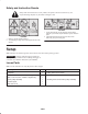
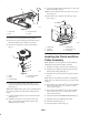
Safety and Instruction Decals Safety decals and instructions are easily visible to the operator and are located near any area of potential danger. Replace any decal that is damaged or lost. 106-5856 1. Thrown object hazard—do not operate the mower with the deflector up or removed; keep the deflector or grass collector in place. 2. Cutting/dismemberment hazard of hand or foot, mower blade—stay away from moving parts. 106-5855 1. Warning—read the Operator’s Manual. 2.
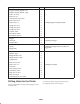
Description Qty. Bagger mounting bracket—left 1 Bagger mounting bracket—right 1 Bolt, 1/4 x 3/4 in. 2 Bolt, 3/8 x 1 in. 4 Carriage bolt, 3/8 x 7/8 in. 4 Bolt, 5/16 x 3/4 in. 4 Bolt, 5/16 x 1 in. 4 Flange nut, 1/4 in. 2 Flange nut, 5/16 in. 8 Flange nut, 3/8 in. 4 Locknut, 3/8 in. 4 Flat washer, 3/8 in. 4 Flat washer, 5/16 in.
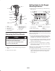
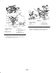
9. Using the template, drill the remaining two 1/8 in. pilot holes into the pulley (Fig. 4). 1 3 10. Remove the template and the screw (#6 x 1/2 in.) and discard (Fig. 4). 11. Drill 3 holes, 3/8 in. diameter, into the 1/8 in. pilot holes. (Fig. 4). 4 5 2 2 m–4119 Figure 2 1. Clutch strap 2. Bolt 3. Clutch connector 4. Clutch 6 1 3 4 3 3. Remove the existing deck belt from the clutch. 4. Remove the existing clutch from the machine (Fig. 3). Discard the bolt that was installed in the clutch.
Drilling Holes for the Bagger Mounting Brackets 1 2 1. Remove the rear heat shield (Fig. 6). Discard the top bolts and nuts. 3 1 4 3 5 2 8 6 or 7 5 4 6 or 7 m–6007 m–5836 Figure 5 1. 2. 3. 4. 5. Figure 6 6. Bolt, 7/16 x 5–1/2 in. for Kawasaki engines 7. Bolt, 7/16 x 4–3/4 in. for Kohler engines 8. Drive spacer Clutch Clutch connector Pulley spacer Drive pulley assembly Curved washers 1. Rear heat shield 2. Bolts—remove and save 3. Top bolts—remove and discard 4.
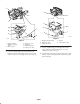
5 4 4 1 1 4 3 5 3 1 6 1 2 4 2 m–6028 Figure 8 m–6031 1. Bagger mounting bracket 2. Bolt, 5/16 x 3/4 in. 3. Flange nut, 5/16 in. Figure 7 1. Bagger mounting bracket—right–hand shown 2. Bolt, 1/4 x 3/4 in. 3. 4. 5. 6. Flange nut, 1/4 in. Side frame Engine guard strap Existing 1/4 in. hole 4. Bumper 5. Flat washers, 5/16 in. 7. Loosely, install the bagger mounting bracket to the engine guard strap with 2 bolts (5/16 x 1 in.) and 2 flange nuts (5/16 in.) (Fig. 9). 6.
3 1 1 2 2 3 4 5 5 2 4 m–6021 Figure 10 5 1. Bagger mounting bracket 2. Drill 13/32 in. hole 3. Rear bumper 4 4. Side frame 5. Existing 1/4 in. hole m–6099 Figure 9 1. Bagger mounting bracket 2. Bolt, 5/16 x 1 in. 3. Flange nut, 5/16 in. Installing the Bagger Mounting Brackets 4. Engine guard strap 5. Bumper Important Do not tighten any bolts until both bagger mounting brackets are fit loose on the machine. 9.
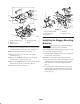
3 1 4 2 7 1 6 3 5 4 m–6021 8 Figure 12 5 4 1. Bagger mounting bracket—right–hand shown 2. Bolt, 3/8 x 1 in. 2 1 m–6019 Figure 11 1. Bagger mounting bracket—right–hand shown 2. Bolt, 1/4 x 3/4 in. 3. Flange nut, 1/4 in. 4. 5. 6. 7. 8. 3. Locknut, 3/8 in. 4. Rear bumper side 5. Flat washer, 3/8 in. 5. Install the bagger mounting bracket to the bottom rear bumper with 2 bolts (5/16 x 3/4 in.), 4 flat washers (5/16 in.), and 2 flange nuts (5/16 in.) (Fig. 13).
3 4 4 1 2 1 6 4 3 5 1 2 4 Figure 13 1. Bagger mounting bracket 2. Bolt, 5/16 x 3/4 in. 3. Flange nut, 5/16 in. 5 1 m–6028 m–6029 Figure 14 4. Bumper 5. Flat washers, 5/16 in. 1. Bagger mounting bracket 2. Bolt, 5/16 x 1 in. 3. Flange nut, 5/16 in. 6. Install the bottom of the rear heat shield to the rear bumper (Fig. 6). 4. Rear heat shield 5. Engine guard strap 6. Rear bumper Tightening all Mounting Bolts 7.
4. Tighten the bagger mounting bracket to the side frame (Fig. 11). See torque table. 5 5. Install the drive wheels. 1 6. Lower the machine onto the drive wheels. Installing the Hydraulic Tank Heat Shield on International Machines 8 3 7 Note: This section is for international machines only. 6 1. Before installing the hydraulic tank heat shield, cut out a section of the heat shield as shown in figure 15. This will allow the heat shield to fit around the side bracket. 2 4 m–6120 Figure 16 1. 2.
3 7 5 8 2 4 1 1 3 2 4 6 m–6032 Figure 18 Figure 17 1. Bagger 2. Bagger mounting bracket m–6008 1. 2. 3. 4. 3. Hairpin cotter pin 4. Clevis pin Bolt, 3/8 x 2–1/4 in. Tensioner pulley and arm Lock nut, 3/8 in. Washer, 3/8 in. 5. 6. 7. 8. Bagger Skid plate Bagger pulley Spacer 5. Install the tensioner spring onto the bolt attached to the bagger (Fig. 20). Installing the Tensioner Pulley and Belt Note: Make sure the bolt for the spring is set at 2 in. (Fig. 19). 1.
2 1 7 6 2 4 3 5 1 1 3 m–6092 Figure 19 1. Bolt for spring 2. Jam nut 3. 2 in. 6 m–6004 Figure 20 6. Install the spring onto the tensioner pulley arm hook (Fig. 20). 1. 2. 3. 4. 7. Install the skid plate (Fig. 18). Tensioner spring Bolt for spring Bagger tensioner pulley Bagger pulley 5. Bagger belt 6. Clutch drive pulley 7. Clutch Installing the Weights Note: There are left hand and right hand weights and weight brackets (Fig. 22).
6 4 5 4 11 10 7 2 6 3 12 1 8 7 1 4 7 2 8 3 5 5 5 9 m–6048 m–6047 Figure 21 1. 2. 3. 4. Front floorpan Footrest Front frame Bolt 5. 6. 7. 8. Figure 22 Nut Washer Front caster wheel Carrier frame 1. 2. 3. 4. 5. 6. 3. With the two holes towards the front, place the left and right–hand weight brackets onto the front frame (Fig. 22). Weight—left Weight—right Weight bracket—left Weight bracket—right Center hole Rear hole 7. 8. 9. 10. 11. 12. Flat washer, 3/8 in. Lock washer, 3/8 in.
6 1 11 2 12 5 3 8 2 11 3 12 5 4 9 m–6111 Figure 23 1. Flange nut, 5/16 in. 2. Bolt, 5/16 x 1 in. 3. Existing flat washer, 5/16 in. 10 4. Front floorpan 5. Support plate 6. Hole to drill if needed 5 6 4 9. Using the support plate as a template, drill one 5/16 in. hole into the front floorpan (Fig. 24). 1 7 m–6050 Figure 24 10. Install a self tapping bolt (3/8 x 5/8 in.) into support plate and hole just drilled (Fig. 24). 1. 2. 3. 4. 5. 6. 7. 11.
3. Tighten the nuts on both sides of the stop bracket (Fig. 26). 5. Position the boot’s front hook into the front slot on the mounting bracket (Fig. 25). 6. Place the rear hook over the rear of the mounting bracket (Fig. 25). 1 7. Install the upper tube into the bagger (Fig. 25). 8. Slide the clamp onto the middle tube (Fig. 25). 4 9. Align the knob on the middle tube with the notch in the upper tube. Slide the middle tube into the upper tube and twist the middle tube 60 degrees (Fig. 25). 10.
Opening the Bagger Important Set the parking brake, and chock or block the tires when leaving the machine unattended, even if just for a few minutes. Important Contact an Authorized Service Dealer for the required dump handle kit when operating this bagger on a machine with a Rollover Protection System (ROPS). Warning 1. Disengage the PTO. To avoid personal injury, follow these procedures: 2. Reach back, squeeze and release the latch lever against the bagger lever (Fig. 28).
Removing the Discharge Tubes 1. Disengage the PTO, set the parking brake, and chock or block the tires. Note: Remember to install the grass deflector when in side discharge mode. Refer to Installing the Grass Deflector on page 20. 2. Stop the engine, remove the key, and wait for all moving parts to stop before leaving the operating position. 1. Disengage the PTO, set the parking brake, and chock or block the drive wheels. 3. Open the bagger; refer to Opening the Bagger, page 18. 4.
9. Install the grass deflector. Refer to Installing the Grass Deflector on page 20. 8 6 4 10. Remove both front weights (Figures 22 and 24). 2 Installing the Grass Deflector 3 5 1 10 The grass deflector spring will have either an L end or a straight end (Fig. 30). Note: Make sure the grass deflector is installed when the bagger and tubes are removed.
Cutting Frequency Signs of Plugging Cut the grass often, especially when it grows rapidly. You will have to cut your grass twice if it gets excessively long (refer to Bagging Long Grass, page 21). As you are bagging, a small amount of grass clippings normally blow out the front of the mower. An excessive amount of clipping blow-out indicates that the bagger is full or the boot is plugged.
Maintenance Important If the machine is on a slope, set the parking brake and chock or block the wheels to prevent the machine from slowly rolling.
Inspecting the Mower Blades and Baffles 2. Inspect the bagger attachment for damage. Refer to Inspecting the Bagger Attachment on page 22. 3. Make sure the bagger is empty and thoroughly dry. 1. Inspect the mower blades and baffles regularly and whenever a blade strikes a foreign object. 4. Check the belt for wear or cracks. 2. If blades or baffles are badly worn or damaged, install new blades or baffles. Refer to your mower operator’s manual for complete blade maintenance. 5.
Problem Boot and tubes plug g too frequently. q y Debris blowout. Possible Causes Corrective Action 1. Hopper is too full. 1. Dump more frequently. 2. Low engine speed. 2. Always operate the bagger at full throttle. 3. Grass is too wet. 3. Cut grass when dry. 4. Grass is too long. 4. Cut no more that 2–3 inches or 1/3 of the grass height, which ever is less. 5. Plugged fan screen. 5. Remove debris, leaves or grass clippings from the fan screen. 6. Ground speed is too fast. 6.