
Operator's Manual

10
6
1
5
4
m–6019
3
1
8
7
4
2
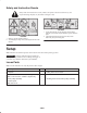
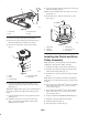
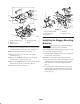
Figure 11
1. Bagger mounting
bracket—right–hand
shown
2. Bolt, 1/4 x 3/4 in.
3. Flange nut, 1/4 in.
4. Side frame
5. Carriage bolt, 3/8 x 7/8 in.
6. Flange nut, 3/8 in.
7. Drilled holes
8. Existing 1/4 in. hole
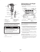
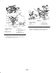
4. Install the bagger mounting bracket to the rear bumper
side with 2 bolts (3/8 x 1 in.), 2 flat washers (3/8 in.),
and 2 locknuts (3/8 in.) (Fig. 12).
2
3
m–6021
1
45
Figure 12
1. Bagger mounting
bracket—right–hand
shown
2. Bolt, 3/8 x 1 in.
3. Locknut, 3/8 in.
4. Rear bumper side
5. Flat washer, 3/8 in.
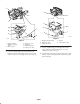
5. Install the bagger mounting bracket to the bottom rear
bumper with 2 bolts (5/16 x 3/4 in.), 4 flat washers
(5/16 in.), and 2 flange nuts (5/16 in.) (Fig. 13).