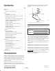
Form No. 3327–680 Bagger 100 Series Z Master Model No. 78490—Serial No.
serial numbers of your product ready. Figure 1 illustrates the location of the model and serial numbers on the product. Contents Introduction . . . . . . . . . . . . . . . . . . . . . . . . . . . . . . . . Safety . . . . . . . . . . . . . . . . . . . . . . . . . . . . . . . . . . . . . Safety and Instruction Decals . . . . . . . . . . . . . . . . Setup . . . . . . . . . . . . . . . . . . . . . . . . . . . . . . . . . . . . . Loose Parts . . . . . . . . . . . . . . . . . . . . . . . . . . . . . .
Safety • Use care when loading or unloading the machine into a trailer or truck The following list contains safety information specific to Toro products and other safety information you must know. • Never operate with the discharge deflector raised, removed or altered, unless using a grass catcher or mulching baffles. • Become familiar with the safe operation of the equipment, with the operator controls, and safety signs. • Keep hands and feet away from moving parts.
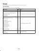
Setup Note: Determine the left and right sides of the machine from the normal operating position. Loose Parts Note: Use the chart below to verify all parts have been shipped. Description Qty. Template 1 Bolt, 7/16 x 5–1/2 in.—Kawasaki engines only Bolt, 7/16 x 4–3/4 in.—Kohler engines only Use Drilling holes into the clutch 1 1 Drive pulley assembly 1 Clutch spacer 1 Bolt, #6 x1/2 in. 1 Bagger mounting bracket—left 1 Bagger mounting bracket—right 1 Bolt, 1/4 x 3/4 in.
Description Qty. Tensioner pulley and arm with hardware 1 Spring 1 Bagger belt 1 Weight—left 1 Weight—right 1 Weight bracket—left 2 Weight bracket—right 2 Support plate 1 Bolt, 3/8 x 6 in. 4 Bolt, 5/16 x 1 in. 2 Nut, 3/8 in. 8 Lock washer, 3/8 in. 8 Flat washer, 3/8 in. 16 Bolt, 3/8 x 4–1/4 in. 4 Bolt, 3/8 x 3/4 in. 2 Self tapping bolt, 3/8 x 5/8 in.
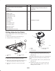
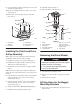
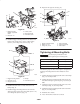
8. Install the clutch strap (Fig. 2). 9. Using the template, drill the remaining two 1/8 in. pilot holes into the pulley (Fig. 4). 9. Plug in the clutch connector (Fig. 2). 10. Remove the template and the screw (#6 x 1/2 in.) and discard (Fig. 4). 1 11. Drill 3 holes, 3/8 in. diameter, into the 1/8 in. pilot holes. (Fig. 4). 2 5 3 2 4 6 1 3 5 8 4 6 or 7 5 3 6 or 7 m–6006 m–6007 Figure 4 1. Clutch pulley 2. Template 3. Hole to drill Figure 5 4. Clutch flange 5. Screw, #6 x 1/2 in. 6.
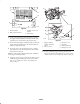
5 1 3 4 2 1 4 m–5836 3 1 Figure 6 1. Rear heat shield 2. Bolts—remove and save 6 3. Top bolts—remove and discard 4. Rear bumper 4 2 2. For the right–hand bagger mounting bracket, position the bagger mounting bracket inside the hydraulic tank, hydraulic hoses, and under the engine guard strap. m–6031 Figure 7 3. For the left–hand bagger mounting bracket, position the bagger mounting bracket inside the exhaust guard and under the engine guard strap. 1. Bagger mounting bracket—right–hand shown 2.
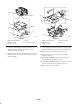
3 4 1 1 2 4 5 4 3 5 1 2 5 4 m–6099 m–6028 Figure 8 1. Bagger mounting bracket 2. Bolt, 5/16 x 3/4 in. 3. Flange nut, 5/16 in. Figure 9 4. Bumper 5. Flat washers, 5/16 in. 1. Bagger mounting bracket 2. Bolt, 5/16 x 1 in. 3. Flange nut, 5/16 in. 7. Loosely, install the bagger mounting bracket to the engine guard strap with 2 bolts (5/16 x 1 in.) and 2 flange nuts (5/16 in.) (Fig. 9). 4. Engine guard strap 5. Bumper 9.
1 4 2 3 7 1 5 6 2 3 4 m–6021 8 Figure 10 1. Bagger mounting bracket 2. Drill 13/32 in. hole 3. Rear bumper 4. Side frame 5. Existing 1/4 in. hole 5 4 2 1 m–6019 Figure 11 Installing the Bagger Mounting Brackets 1. Bagger mounting bracket—right–hand shown 2. Bolt, 1/4 x 3/4 in. 3. Flange nut, 1/4 in. Important Do not tighten any bolts until both bagger mounting brackets are fit loose on the machine.
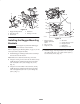
8. Repeat for the opposite side (Fig. 14). 3 3 4 1 1 2 2 6 5 4 m–6021 Figure 12 1. Bagger mounting bracket—right–hand shown 2. Bolt, 3/8 x 1 in. 3. Locknut, 3/8 in. 4. Rear bumper side 5. Flat washer, 3/8 in. 4 5 1 5. Install the bagger mounting bracket to the bottom rear bumper with 2 bolts (5/16 x 3/4 in.), 4 flat washers (5/16 in.), and 2 flange nuts (5/16 in.) (Fig. 13). m–6029 Figure 14 1. Bagger mounting bracket 2. Bolt, 5/16 x 1 in. 3. Flange nut, 5/16 in. 4. Rear heat shield 5.
Installing the Bagger 1. Remove the four bolts in the skid plate (Fig. 16). 3 7 2. Remove the skid plate (Fig. 16). This will make it easier to install the bagger belt. 5 8 3. Install the bagger onto the bagger mounting bracket (Fig. 15). 2 4. Install clevis pins into the bagger and bagger mounting bracket. Secure with hairpin cotter pins (Fig. 15). 4 1 6 m–6008 Figure 16 1. 2. 3. 4. 1 Bolt, 3/8 x 2–1/4 in. Tensioner pulley and arm Lock nut, 3/8 in. Washer, 3/8 in. 5. 6. 7. 8.
7. Install the skid plate (Fig. 16). 1. Remove the two outside bolts that connect the front floorpan to the carrier frame (Fig. 19). Save this hardware. 2. Remove the 4 bolts and washers that hold the front floorpan to the front frame (Fig. 19). Save this hardware. 2 6 4 4 2 1 7 6 4 1 5 8 7 1 3 6 m–6004 3 Figure 18 1. 2. 3. 4. Tensioner spring Bolt for spring Bagger tensioner pulley Bagger pulley 5. Bagger belt 6. Clutch drive pulley 7. Clutch 5 5 5 m–6047 Figure 19 1. 2. 3. 4.
5 11 10 11 2 12 5 7 3 6 3 8 12 11 12 9 10 1 4 7 2 5 6 4 8 9 1. 2. 3. 4. 5. 6. 7. Figure 20 Weight—left Weight—right Weight bracket—left Weight bracket—right Center hole Rear hole 7. 8. 9. 10. 11. 12. m–6050 Figure 21 m–6048 1. 2. 3. 4. 5. 6. 1 7 Flat washer, 3/8 in. Lock washer, 3/8 in. Nut, 3/8 in. Bolt, 3/8 in. x 6 in. Bolt, 3/8 in. x 3/4 in. Front frame 6. Install the two outside bolts that connect the front floorpan to the carrier frame (Fig. 19). Weight Bolt, 3/8 x 4–1/4 in.
9. Align the knob on the middle tube with the notch in the upper tube. Slide the middle tube into the upper tube and twist the middle tube 60 degrees (Fig. 22). 1 10. Tighten the clamp around the upper and middle tube connection (Fig. 22). 4 11. Slide the middle tube onto the boot and latch them together (Fig. 22). 11 1 3 5 4 2 6 5 2 3 5 m–6071 9 1 Figure 23 1. Bagger lever 2. Stop bracket 3. Stop bolt 10 Checking the Tire Pressure 8 Check the air pressure in the front caster wheel (Fig.
Opening the Bagger Important Set the parking brake, and chock or block the tires when leaving the machine unattended, even if just for a few minutes. 1. Disengage the PTO. 2. Reach back, squeeze and release the latch lever against the bagger lever (Fig. 25). This will open the latch that secures the bagger door. Warning To avoid personal injury, follow these procedures: 3. Pull down on the bagger arm to allow the grass to fall out of the bagger (Fig. 25).
3. Open the bagger; refer to Opening the Bagger, page 15. 3. Unlatch the middle tube from the boot and slide apart (Fig. 22). 4. With the bagger open, pull out the holding pin and insert into the hole in the hinge (Fig. 26). 4. Remove the tube assembly from the bagger (Fig. 22). 5. Remove the boot from the mounting bracket (Fig. 22). 6. If you are changing to side discharge mode, install the grass deflector. Refer to Installing the Grass Deflector on page 16.
Operating and Bagging Tips Warning Machine Size An uncovered discharge opening could allow the lawn mower to throw objects in the operator’s or bystander’s direction and result in serious injury. Also, contact with the blade could occur. Remember that the machine is longer and wider with this attachment installed. By turning too sharply in confined places you may damage the attachment or other property.
Caution Warning As the bagger fills, extra weight is added to the back of the machine. If you stop and start suddenly on hills, you may lose steering control or the machine may tip. Without the grass deflector, bagger tubes or complete bagger assembly mounted in place, you and others are exposed to blade contact and thrown debris. Contact with the rotating mower blade(s) and thrown debris will cause injury or death. • Do not start or stop suddenly when going uphill or downhill. Avoid uphill starts.
Maintenance Important If the machine is on a slope, set the parking brake and chock or block the wheels to prevent the machine from slowly rolling.
Inspecting the Mower Blades and Baffles 2. Inspect the bagger attachment for damage. Refer to Inspecting the Bagger Attachment on page 19. 3. Make sure the bagger is empty and thoroughly dry. 1. Inspect the mower blades and baffles regularly and whenever a blade strikes a foreign object. 4. Check the belt for wear or cracks. 2. If blades or baffles are badly worn or damaged, install new blades or baffles. Refer to your mower operator’s manual for complete blade maintenance. 5.
Problem Boot and tubes plug g too frequently. q y Debris blowout. Possible Causes Corrective Action 1. Hopper is too full. 1. Dump more frequently. 2. Low engine speed. 2. Always operate the bagger at full throttle. 3. Grass is too wet. 3. Cut grass when dry. 4. Grass is too long. 4. Cut no more that 2–3 inches or 1/3 of the grass height, which ever is less. 5. Plugged fan screen. 5. Remove debris, leaves or grass clippings from the fan screen. 6. Ground speed is too fast. 6.