
Operator's Manual

10
2
3
m–6021
1
45
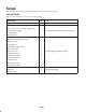
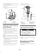
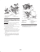
Figure 12
1. Bagger mounting
bracket—right–hand
shown
2. Bolt, 3/8 x 1 in.
3. Locknut, 3/8 in.
4. Rear bumper side
5. Flat washer, 3/8 in.
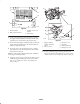
5. Install the bagger mounting bracket to the bottom rear
bumper with 2 bolts (5/16 x 3/4 in.), 4 flat washers
(5/16 in.), and 2 flange nuts (5/16 in.) (Fig. 13).
m–6028
1
1
4
2
4
3
5
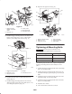
Figure 13
1. Bagger mounting bracket
2. Bolt, 5/16 x 3/4 in.
3. Flange nut, 5/16 in.
4. Bumper
5. Flat washers, 5/16 in.
6. Install the bottom of the rear heat shield to the rear
bumper (Fig. 6).
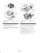
7. Install the bagger mounting bracket to the rear heat
shield and engine guard strap with 2 bolts (5/16 x 1 in.)
and 2 flange nuts (5/16 in.) (Fig. 14).
8. Repeat for the opposite side (Fig. 14).
4
5
1
3
2
4
m–6029
1
6
Figure 14
1. Bagger mounting bracket
2. Bolt, 5/16 x 1 in.
3. Flange nut, 5/16 in.
4. Rear heat shield
5. Engine guard strap
6. Rear bumper
Tightening all Mounting Bolts
Important Use the torque specifications in the
following table when tightening the mounting bolts.
Size of mounting bolts Torque
All 5/16 in. bolts
230 in.–lb. (26 Nm)
All 3/8 in. bolts
35 ft.–lb. (48 Nm)
All 1/4 in. bolts
100 in.–lb. (11 Nm)
The following steps are the correct sequence to tighten the
the bagger mounting brackets when all fasteners are in
place.
1. Tighten the bagger mounting bracket to the rear bumper
(Fig. 13). See torque table.
2. Tighten the bagger mounting bracket to the upper rear
heat shield and engine guard strap (Fig. 14). See torque
table.
3. Tighten the bagger mounting bracket to the side of the
rear bumper (Fig. 12). See torque table.
4. Tighten the bagger mounting bracket to the side frame
(Fig. 11). See torque table.
5. Install the drive wheels.
6. Lower the machine onto the drive wheels.