
Operator's Manual

4
Setup
Note: Determine the left and right sides of the machine from the normal operating position.
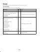
Loose Parts
Note: Use the chart below to verify all parts have been shipped.
Description Qty. Use
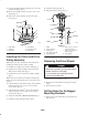
Template 1 Drilling holes into the clutch
Bolt, 7/16 x 5–1/2 in.—Kawasaki
engines only
Bolt, 7/16 x 4–3/4 in.—Kohler
engines only
Drive pulley assembly
Clutch spacer
Bolt, #6 x1/2 in.
1
1
1
1
1
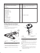
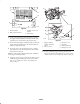
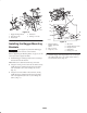
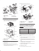
Installing the clutch and drive pulley assembly
Bagger mounting bracket—left
Bagger mounting bracket—right
Bolt, 1/4 x 3/4 in.
Bolt, 3/8 x 1 in.
Carriage bolt, 3/8 x 7/8 in.
Bolt, 5/16 x 3/4 in.
Bolt, 5/16 x 1 in.
Flange nut, 1/4 in.
Flange nut, 5/16 in.
Flange nut, 3/8 in.
Locknut, 3/8 in.
Flat washer, 3/8 in.
Flat washer, 5/16 in.
1
1
2
4
4
4
4
2
8
4
4
4
8
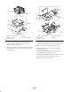
Installing bagger mounting brackets
Bagger
Clevis pin
Hairpin cotter
1
2
2
Installing the bagger