
Operator's Manual

6
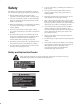
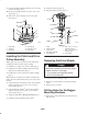
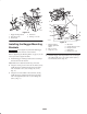
9. Using the template, drill the remaining two 1/8 in. pilot
holes into the pulley (Fig. 4).
10. Remove the template and the screw (#6 x 1/2 in.) and
discard (Fig. 4).
11. Drill 3 holes, 3/8 in. diameter, into the 1/8 in. pilot
holes. (Fig. 4).
m–6006
2
3
3
1
4
5
6
Figure 4
1. Clutch pulley
2. Template
3. Hole to drill
4. Clutch flange
5. Screw, #6 x 1/2 in.
6. Drive spacer
Installing the Clutch and Drive
Pulley Assembly
Note: Apply anti–seize compound to crank shaft before
installing the clutch and drive pulley assembly.
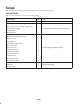
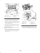
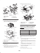
1. Install the new pulley spacer into the clutch (Fig. 5).
2. Install the drive pulley assembly into the three holes
drilled into the clutch pulley (Fig. 5).
3. Install the drive spacer into the drive pulley assembly
(Fig. 5).
Note: There are two different size bolts for installing the
clutch. The size is determined by the type of engine on the
machine.
4. If the machine has a Kawasaki
engine, then install the
clutch with a bolt, 7/16 x 5–1/2 in., and 2 existing
curved washers (Fig. 5).
5. If the machine has a Kohler
engine, then install the
clutch with a bolt, 7/16 x 4–3/4 in., and 2 existing
curved washers (Fig. 5).
6. Torque the clutch bolt to 55 ft.–lb. (75 Nm) (Fig. 5).
7. Install the existing deck belt onto the clutch.
8. Install the clutch strap (Fig. 2).
9. Plug in the clutch connector (Fig. 2).
m–6007
4
3
5
6 or 7
2
1
5
6 or 7
8
Figure 5
1. Clutch
2. Clutch connector
3. Pulley spacer
4. Drive pulley assembly
5. Curved washers
6. Bolt, 7/16 x 5–1/2 in. for
Kawasaki engines
7. Bolt, 7/16 x 4–3/4 in. for
Kohler engines
8. Drive spacer
Removing the Drive Wheels
Danger
Mechanical or hydraulic jacks may fail to support
machine and cause a serious injury.
• Use jack stands when supporting machine.
• Do not use hydraulic jacks.
1. Loosen the drive wheel lugs or nuts.
2. Raise the rear of the machine and support with jack
stands.
3. Remove the drive wheels.
Drilling Holes for the Bagger
Mounting Brackets
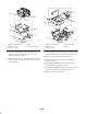
1. Remove the rear heat shield (Fig. 6). Discard the top
bolts and nuts.