
Operator's Manual

7
m–5836
2
1
3
4
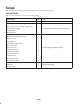
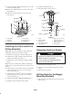
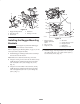
Figure 6
1. Rear heat shield
2. Bolts—remove and save
3. Top bolts—remove and
discard
4. Rear bumper
2. For the right–hand bagger mounting bracket, position
the bagger mounting bracket inside the hydraulic tank,
hydraulic hoses, and under the engine guard strap.
3. For the left–hand bagger mounting bracket, position the
bagger mounting bracket inside the exhaust guard and
under the engine guard strap.
4. If present, remove the existing bolt (1/4 in.), holding
electrical relays to the left or right–hand side of frame.
Discard the nut and bolt.
Note: The relays will be installed during final installation
of the bagger mounting brackets.
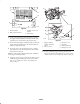
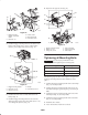
5. Using the existing 1/4 in. hole in the side frame, loosely
install the bagger mounting bracket to the side frame
(Fig. 7). Use 1 bolt (1/4 x 3/4 in.) and 1 flange nut
(1/4 in.) (Fig. 7).
m–6031
1
4
2
3
1
6
5
4
Figure 7
1. Bagger mounting
bracket—right–hand
shown
2. Bolt, 1/4 x 3/4 in.
3. Flange nut, 1/4 in.
4. Side frame
5. Engine guard strap
6. Existing 1/4 in. hole
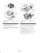
6. Loosely, install the bagger mounting bracket to the
bottom rear bumper with 2 bolts (5/16 x 3/4 in.), 4 flat
washers (5/16 in.), and 2 flange nuts (5/16 in.) (Fig. 8).