
Operator's Manual

8
1
1
4
2
4
3
m–6028
5
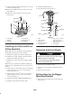
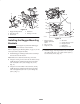
Figure 8
1. Bagger mounting bracket
2. Bolt, 5/16 x 3/4 in.
3. Flange nut, 5/16 in.
4. Bumper
5. Flat washers, 5/16 in.
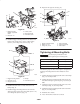
7. Loosely, install the bagger mounting bracket to the
engine guard strap with 2 bolts (5/16 x 1 in.) and
2 flange nuts (5/16 in.) (Fig. 9).
8. Tighten all the bolts and nuts. Start with the 1/4 in. bolt,
then the 5/16 in. rear bumper bolts, and then the engine
guard strap bolts.
4
1
3
2
m–6099
5
5
4
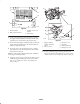
Figure 9
1. Bagger mounting bracket
2. Bolt, 5/16 x 1 in.
3. Flange nut, 5/16 in.
4. Engine guard strap
5. Bumper
9. Using the bagger mounting bracket as a template, mark
the 4 hole locations in the center of the slots (Fig. 10).
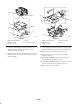
10. Remove the bagger mounting bracket (Fig. 10).
11. Drill 4 pilot holes, 1/8 in. diameter, at the marked
locations. (Fig. 10).
12. Drill 2 holes, 13/32 in. diameter, into the side frame
through the 1/8 in. pilot holes. (Fig. 10).
13. Drill 2 holes, 13/32 in. diameter, into the side of the rear
bumper through the 1/8 in. pilot holes. (Fig. 10).
14. Repeat steps for the opposite side.