
Operator's Manual

9
m–6021
1
2
5
2
3
4
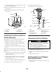
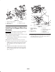
Figure 10
1. Bagger mounting bracket
2. Drill 13/32 in. hole
3. Rear bumper
4. Side frame
5. Existing 1/4 in. hole
Installing the Bagger Mounting
Brackets
Important Do not tighten any bolts until both bagger
mounting brackets are fit loose on the machine.
Refer to Tightening the Mounting Bolts, on page 10, for the
correct procedure to tighten the bolts.
1. Install the bagger mounting bracket to the rear bumper
and side frame of the machine.
Note: Make sure to attach electrical relays, if needed.
2. Using the existing 1/4 in. hole in the side frame, loosely
install the bagger mounting bracket to the side frame
with 1 bolt (1/4 x 3/4 in.) and 1 flange nut (1/4 in.)
(Fig. 11).
3. Using the two holes drilled in the side frame, loosely
install the bagger mounting bracket to the side frame
with 2 carriage bolts (3/8 x 7/8 in.) and 2 flange nuts
(3/8 in.) (Fig. 11).
6
1
5
4
m–6019
3
1
8
7
4
2
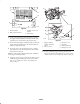
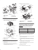
Figure 11
1. Bagger mounting
bracket—right–hand
shown
2. Bolt, 1/4 x 3/4 in.
3. Flange nut, 1/4 in.
4. Side frame
5. Carriage bolt, 3/8 x 7/8 in.
6. Flange nut, 3/8 in.
7. Drilled holes
8. Existing 1/4 in. hole
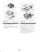
4. Install the bagger mounting bracket to the rear bumper
side with 2 bolts (3/8 x 1 in.), 2 flat washers (3/8 in.),
and 2 locknuts (3/8 in.) (Fig. 12).