Form No. 3352–637 52in TURBO FORCE Mower Finishing Kit Z500 Twin Soft Bagger Model No. 78512 Operator’s Manual Register your product at www.Toro.
Contents Introduction . . . . . . . . . . . . . . . . . . . . . . . . . . . . . . . . Safety . . . . . . . . . . . . . . . . . . . . . . . . . . . . . . . . . . . . . Safety and Instruction Decals . . . . . . . . . . . . . . . Setup . . . . . . . . . . . . . . . . . . . . . . . . . . . . . . . . . . . . . Loose Parts . . . . . . . . . . . . . . . . . . . . . . . . . . . . . . Before Installation . . . . . . . . . . . . . . . . . . . . . . . . . . . Prepare the Mower . . . . . . . . . . . . . . . . . . . . .
• Do not use your hands to unclog the chute, blower or bagger. Caution signals a hazard that may cause minor or moderate injury if you do not follow the recommended precautions. • Do not leave grass in grass catcher for extended periods of time. This manual uses two other words to highlight information. Important calls attention to special mechanical information and Note: emphasizes general information worthy of special attention.
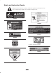
Safety and Instruction Decals Safety decals and instructions are easily visible to the operator and are located near any area of potential danger. Replace any decal that is damaged or lost. 79-0350 1-653554 79-0360 106-0871 80-8040 98-4387 1. Warning—wear hearing protection.
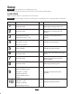
Setup Important These instructions are for Z500 machines only. Note: Determine the left and right sides of the machine from the normal operating position. Loose Parts Note: Use the chart below to verify all parts have been shipped. Important This kit and bagger will require significant time to install the first time. A right angle drill is recommended for installation. Step 1 2 3 4 5 6 7 8 9 10 Description Qty.
Step Description Qty.
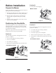
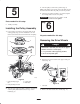
Position B Before Installation Use this position when bagging. Prepare the Mower Middle Position Perform the following procedure to prepare the mower for attaching the blower and finishing kit. 1. Disengage the PTO, move the motion control levers to the neutral locked position and set the parking brake. 2. Stop the engine, remove the key, and wait for all moving parts to stop before leaving the operating position. 3. Clean the mower of any debris on the deck or rear of mower to ease installation.
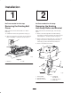
Installation Step Step 1 2 No Parts needed for this step. No Parts needed for this step. Removing the Existing Belt Cover Removing the Existing Anti-Scalp Roller and Bracket Note: Clean the area around the belt cover before removing. Note: Clean the area around the right, rear anti-scalp wheel 1. Unlatch and remove the right belt cover (Fig. 5). 1.
Step Step 3 4 Parts needed for this step: Parts needed for this step: • 1 Anti-scalp roller bracket • 1 Mounting plate • 1 Tapping screw • 2 Bolts, 3/8 x 1-1/4 inch • 3 Carriage bolt, 3/8 x 1 inch • 2 Flange nuts, 3/8 inch Installing the New Bracket and Anti-Scalp Roller Installing the Mounting Plate 1. Install the new anti–scalp roller bracket using the three carriage bolts (3/8 x 1 inch) and flange nuts (3/8 inch) removed previously (Fig. 7).
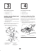
3. Turn the pulley to lock it into position (Fig. 9). Step 5 Note: If the pulley does not turn, loosen the bolts to raise the bolt heads and allow the pulley to lock into position. 4. After the new pulley assembly is in position, tighten the existing bolts to secure new pulley. Important Torque the nuts to 23 ft-lb ± 2 ft-lb (31 N⋅m ± 3 N⋅m). Do not over tighten. Parts needed for this step: Step • 1 Pulley assembly Installing the Pulley Assembly 1.
2. Remove the hair pin cotters and pins securing the center roll bar section to the right and left sections (Fig. 13). 1 m–6859 1 Figure 11 1. Drive wheel Step 2 7 m–6893 Figure 13 1. Pin 2. Hair pin cotter 3. Loosen the center roll bar bolts allowing the roll bar to be pivoted to the down position (Fig. 14). No parts needed for this step. Removing the Roll Over Protection System (ROPS) 1. Loosen the front handles securing the center roll bar section to the right and left sections (Fig. 12).
5. Remove the following fasteners (Fig. 15) securing each (right and left) roll bar section to the frame: Step • Lock nut (3/8 inch) and curved washer. Do not remove bolt from frame. • Bolt (3/8 x 1 inch), curved washer and flange nut (3/8 inch). 8 • Bolt (3/8 x 1 inch), curved washer and flange nut (3/8 inch). No parts needed for this step. • Bolt (3/8 x 4-1/2 inches), curved washer and flange nut (3/8 inch).
Step 9 5 4 7 6 3 2 2 7 5 Parts needed for this step: • 1 Left side bagger bracket • 1 Right side bagger bracket • 6 Bolt, 3/8 x 1–1/2 inch m–7628 • 6 Flange Nut, 3/8 inch 2 5 1 Figure 17 1. Bagger bracket-(right side shown) 2. Bolt, 3/8 x 1–1/2 inch 3. Flange nut, 3/8 inch 4. Machine side frame • 6 Curved washer • 4 Spacer Installing the Side Brackets to the Machine 5. Belleville washer, 3/8 inch 6. Rollover Protection System (ROPS) 7. Spacer 2.
1 2 1 m–6891 m–6891 Figure 19 Figure 21 1. Center roll bar section 1. Bolt 2. Flange nut 5. Raise the roll bar into the upright position and secure it with the pins and hairpin cotter pins fastened to the lanyards (Fig. 20). 7. Torque all lower fasteners, attached to the machine frame, to 30 ft–lb. 8. Tighten the front handles against the center roll bar ends. 1 2 m–6893 Figure 20 1. Pin 1 2. Hair pin cotter 6.
Step 5 2 10 3 1 2 4 Parts needed for this step: • 1 Bagger mounting bracket 6 • 6 Bolts, 3/8 x 1 inch • 6 Flange nuts, 3/8 inch 3 4 2 m–6743 • 6 Belleville washers, 3/8 inch Figure 23 Installing the Bagger Mounting Bracket 1. Bagger mounting bracket 2. Bolt, 3/8 x 1 inch 3. Flange nut, 3/8 inch Note: For diesel engines, contact an Authorized Service Dealer for a Triple Bagger Mounting Kit. 4. Belleville washer, 3/8 inch 5. Rear frame 6. Existing bolts located here 2.
1. Install the hood assembly onto the bagger mounting bracket (Fig. 24). Step 11 Parts needed for this step: 2 • 1 Hood assembly 1 • 2 Bags • 2 Clevis pins • 2 Hairpin cotter pins m–6758 Figure 24 Installing the Hood Assembly and Bags 1. Hood assembly 2. Bagger mounting bracket 2. Install the 2 clevis pins into the hood assembly and bagger mounting bracket. Secure it with 2 hairpin cotter pins (Fig. 25). Warning Components around engine will be hot if the machine has been running.
3. Install the bag tab into the notch in the hood assembly (Fig. 26). Do this for both bags. 1 Note: The bag will rest on the bagger frame (Fig. 26). 3 2 4 5 m–6264 Figure 28 1. Bagger latch 1 3 2 m–6760 Figure 26 1. Hood assembly 2. Bag 3. Bag tab 4. Notch 5. Bagger frame 4. Lower the bagger hood over the bags (Fig. 27). 1 3 4 2 m–6761 Figure 27 1. Hood 2. Bags 3. Bagger latch 4. Latch hook 5. Position the bagger latch under the latch hook (Figures 27 and 28). 6.
Step Step 12 13 Parts needed for this step: Parts needed for this step: • 1 Blower assembly • 1 Blower belt cover • 1 Idler spring Installing the Blower Assembly • 1 Bagger belt Important Make sure the mounting plate is installed to the mower. • 1 Pulley cover 1. Move the grass deflector into the upright position. Installing the Bagger Belt and Idler Spring 2. Slide the blower assembly peg into the hole on the bracket (Fig. 29).
3 4 6 2 m–7007 7 1 5 Figure 31 1. Blower pulley 2. Mower 3. Blower assembly 4. Top pulley of mower pulley assembly 5. Spring loaded idler pulley (belt back side touching pulley) 6. Fixed idler pulley 7. Front latch (red) 4. Push down on the front latch (colored red) and open the blower assembly (Fig. 31). 5. Install the bagger belt on the top mower pulley (Fig. 31). 6. Route the bagger belt around the top pulley of the mower pulley assembly (Fig. 31). 7.
13. Install the belt cover over the pulley assembly and secure the 3 cover latches into the blower (Fig. 33). 3 Step 14 2 Parts needed for this step: • 1 Belt cover 1 Installing the Belt Cover 1. Install the new belt cover over the pulley assembly and secure the latches (Fig. 34). 2 3 m–6236 1 Figure 33 1. Blower assembly 2. Blower belt cover 3. Latch m–7811 Figure 34 1. Pulley assembly 2. Belt cover 20 3.
Step 4 15 1 3 4 5 Parts needed for this step: 2 • 1 Bagger tube • 1 Clamp • 2 Knobs m–6252 • 1 Blower adapter Figure 36 1. Tube 2. Blower assembly 3. Top blower stud Installing the Bagger Tube Note: To ease assembly of the bagger tube to the blower adapter, apply a little soapy water to both the bagger tube and the adapter. 4. Knob 5. Side blower stud Note: There are nubs on the inside of the bagger hood that hold the upper end of the bagger tube (Fig. 37). 1.
Step 2 16 1 3 1 6 4 Parts needed for this step: 5 • 2 Caster weights • 2 Top weights • 2 U–bolts m–5882 • 4 Nuts, 1/2 inch Figure 38 • 2 Plates 1. Front caster weight 2. U–bolt 3. Plate • 4 Lock washers, 1/2 inch 4. Nut 5. Front caster 6. Lock washer • 2 Bolts, 1/2 x 3 inch Installing the Extra Top Weight Installing the Weights 1. Install the top weight on top of the caster weight with a bolt (1/2 x 3 inch) (Fig. 39). To comply with ANSI/OPEI B71.
Checking the Tire Pressure 4 5 7 Check and adjust the air pressure in the front and rear tires. 6 Pressure: 13 psi (90 kPa) drive wheels and caster wheels (Fig. 39). 1 1 3 2 m–3788 Figure 41 1. Brake lever 2. Spring 2–5/8 inch (67 mm) 3. Adjusting nut and jam nut below the spring m–1872 4. 5. 6. 7. Collar on brake rod 5/16 inch (8 mm) Yoke and jam nut Trunnion roller Figure 40 1. Valve stem 3.
Operation Note: Determine the left and right sides of the machine from the normal operating position. Caution Important Set the parking brake when leaving the machine unattended, even for just a few minutes. Children or bystanders may be injured if they move or attempt to operate the machine while it is unattended. Warning Always remove the ignition key and set the parking brake when leaving the machine unattended, even for just a few minutes.
Transporting Machines 8. Lower the bagger hood over the bags (Fig. 27). 9. Latch the bagger hood (Fig. 28). Do not leave grass or debris in the bagger while transporting the machine. Clearing Obstructions From the Bagger System Warning Transporting the machine with grass or debris in the bagger can damage the machine. Danger Do not leave grass or debris in the bagger while transporting the machine. When the bagger is in operation, the blower can be rotating and cut off or injure hands.
Caution As the bagger fills, extra weight is added to the back of the machine. If you stop and start suddenly on hills, you may lose steering control or the machine may tip. • Do not start or stop suddenly when going uphill or downhill. Avoid uphill starts. • If you do stop the machine when going uphill, disengage the PTO. Then back down the hill using a slow speed. • Do not change speeds or stop on slopes.
Maintenance Important If the machine is on a slope and set the parking brake to prevent the machine from slowly rolling.
3. Close the blower assembly and measure between the spring coil ends. See Figure 43 for measuring the spring length and eye hook orientation. 2 3 6 4 5 1 5 2 2 m–7781 3 Figure 44 1 4 1. Fixed idler 2. Blower assembly 3. Adjust idler to the front to shorten the spring 4. Bolts m–6275 Figure 43 1. Spring 2. End of spring coils 3. Blower assembly peg 4. Distance between spring coil ends, 4 to 4–3/4 inches (102 mm to 121 mm) 5. Eyebolt 5. Adjust idler to the rear to lengthen the spring 6.
Checking and Adjusting the Blower Latch Adjust the blower latch when it is does not engage the front peg correctly. 1. There must not be a gap between the mounting plate the the blower assembly (Fig. 45). If there is a gap, proceed to step 3 and shorten the latch. 3 Top view 4 1 1 2 m–6721 Figure 46 1. Blower front latch (Red) 2. Front peg 3. To adjust the blower latch, loosen the jam nut. (Fig. 47). 2 2 1 m–6268 Figure 45 1. Blower assembly 2. Blower front latch (Red) 3. Gap shown 4.
Replacing the Blower Belt 7. Remove the bagger belt from the blower assembly pulley (Fig. 49). Check the bagger belt for wear and cracks after the first 8 hours and then every 25 hours. 4 3 6 1. Disengage the PTO and set the parking brake. 7 2. Turn off the engine, remove the key, and wait for all moving parts to stop before leaving the operating position. 3. Push down on the front latch and open the blower assembly (Fig. 49). This will automatically remove the tension from the blower belt. 4.
3. Remove the blower adapter and tube from the blower (Fig. 36). 3 4. Remove the five bolts that hold the blower liner to the blower (Figures 50 and 51). 5. Pull the liner out of the blower (Fig. 50). 2 3 2 4 4 1 5 m–6243 Figure 51 1. Blower 2. Bolt 1 m–6244 10. Push the top 2 bolts down, toward the front of blower, until the blower liner conforms to the inside of the blower (Fig. 52). This will provide clearance between the impeller and the liner. Figure 50 1. Blower 2. Liner 3. Bolt 3. Nut 4.
Inspecting the Bagger 2. If blades or baffles are badly worn or damaged, install new blades or baffles. Refer to your mower operator’s manual for complete blade maintenance. Inspect the bagger attachment after the first 8 hours of operation and 100 hours thereafter. 1. Disengage the PTO and set the parking brake. Installing Mower Blades 2. Turn off the engine, remove the key, and wait for all moving parts to stop before leaving the operating position.
Troubleshooting Problem Abnormal vibration. Reduced bagging performance. Blower and tube plug g too f frequently. tl Debris blowout. Blower impeller does not spin freely. Possible Causes Corrective Action 1. Cutting blade(s) bent or unbalanced. 1. Install new cutting blade(s). 2. Blade mounting bolt is loose. 2. Tighten blade mounting bolt. 3. Loose blower pulley or pulley assembly. 3. Tighten the appropriate pulley. 4. Blower belt is worn or damaged. 4. Replace the blower belt. 5.