
Operator's Manual

10
5
Step
Parts needed for this step:
• 1 Pulley assembly
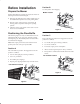
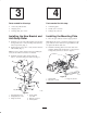
Installing the Pulley Assembly
1. Loosen, but do not remove, the tapping bolts on the
existing pulley (Fig. 9). There should be a 1/4 inch
(0.64 cm) clearance between the bolt head and pulley.
4
1
1/4 inch
2
3
(0.64 cm)
m–7808
Figure 9
1. Pulley assembly, bagger
belt
2. Pulley assembly, drive belt
3. Locking slots
4. Bolts heads
2. Align the new pulley assembly so that the openings fit
over the pulley bolt heads loosened in step 1 and
install (Fig. 9).
3. Turn the pulley to lock it into position (Fig. 9).
Note: If the pulley does not turn, loosen the bolts to raise
the bolt heads and allow the pulley to lock into position.
4. After the new pulley assembly is in position, tighten
the existing bolts to secure new pulley.
Important Torque the nuts to 23 ft-lb ± 2 ft-lb
(31 N⋅m ± 3 N⋅m). Do not over tighten.
6
Step
No parts needed for this step.
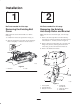
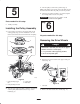
Removing the Drive Wheels
Danger
Mechanical or hydraulic jacks may fail to support
machine and cause a serious injury.
• Use jack stands when supporting machine.
• Do not use hydraulic jacks.
1. Loosen the drive wheel nuts.
2. Raise the rear of the machine and support with jack
stands (Fig. 10).
1
1
Figure 10
1. Jack stand
3. Remove the nuts and the drive wheels (Fig. 11).