Form No. 3423-836 Rev A Twin Bagger Grandstand® Mower Model No. 78524—Serial No. 400000000 and Up Note: Register at www.Toro.com.
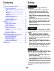
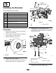
WARNING CALIFORNIA Proposition 65 Warning Use of this product may cause exposure to chemicals known to the State of California to cause cancer, birth defects, or other reproductive harm. g256118 Figure 2 Introduction 1. Bagger model and serial number location Read this information carefully to learn how to operate and maintain your product properly and to avoid injury and product damage. You are responsible for operating the product properly and safely. Model No. Serial No. Visit www.Toro.
Contents Safety Safety ....................................................................... 3 Safety and Instructional Decals .......................... 4 Setup ........................................................................ 6 1 Preparing the Machine..................................... 7 2 Installing the E-Z Vac Blower and Drive Kit.................................................................... 7 3 Installing the Blower Assembly, Belt, and Belt Cover .....................................
• Become familiar with the safe operation of the • Never operate with the discharge deflector raised, equipment, with the operator controls, and safety signs. removed, or altered, unless you are using a grass catcher. • Keep your hands and feet away from moving parts. • Use extra care with grass catchers or other Do not make adjustments with the engine running. attachments. These can change the operating characteristics and the stability of the machine.
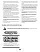
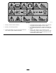
decal136-4087 136-4087 1. Warning—read the Operator’s Manual. 4. Cutting/dismemberment hazard, impeller—keep away from moving parts; keep all guards and covers in place. 2. Warning—wear hearing protection. 5. Cutting/dismemberment hazard, impeller—disengage the PTO, remove the ignition key, and wait for all moving parts to stop. 3. Thrown object hazard—do not run the blower without the entire collection system installed and latched. 6.
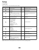
Setup Loose Parts Use the chart below to verify that all parts have been shipped. Procedure 1 2 3 4 5 6 7 8 9 Description Use Qty. No parts required – Prepare the machine. E-Z Vac Blower and Drive Kit (sold separately) 1 Install the E-Z Vac Blower and Drive Kit (sold separately).
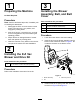
1 3 Preparing the Machine Installing the Blower Assembly, Belt, and Belt Cover No Parts Required Procedure Parts needed for this procedure: Note: Remove the Roller Striper Kit, if installed, prior to installing this attachment. 1. Disengage the PTO, move the motion-control levers to the NEUTRAL-LOCK position, and engage the parking brake. 2. Shut off the engine, remove the key, and wait for all moving parts to stop before leaving the operating position. 3.
decal138-8866 Figure 5 g037529 Figure 7 1. Knob 2. Idler screw 3. Belt cover Note: Whenever you need to open the blower assembly, remove the belt cover first. 4 Installing the Bagger Enhancement Kit (Optional) Parts needed for this procedure: g293335 Figure 6 1. Blower belt 1 2. Mower deck belt 4. Close the blower assembly so that the handle latches on the blower mount. 5. Install the belt cover and secure it by screwing the knob onto the screw on the idler (Figure 7).
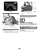
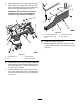
5 Installing the Brackets Parts needed for this procedure: 1 Front mount bracket 1 Lower mount bracket 1 Rear mount bracket 1 Right mount bracket 2 Flat washer 2 Bolt (3/8 x 4 inches) 1 Carriage bolt (3/8 x 1 inch) 1 Nut (3/8 inch) 2 Carriage bolt (1/4 x 5/8 inch) 2 Nut (1/4 inch) g037605 Figure 9 1. Bolt 3. Right transaxle 2. Nut 6. Procedure 1. Remove the fuel tank; refer to the Operator’s Manual for the machine. 2.
8. Torque the bolts to 37 to 45 N∙m (27 to 33 ft-lb). 9. Remove the front 2 bolts and 2 nuts from the right mount bracket and the front 2 bolts and 2 nuts from the right tower panel (Figure 11). Important: Ensure that the fan shroud inside the frame does not fall onto the transaxle as you remove the hardware. g037608 Figure 12 1. Front of the control tower 2. Carriage bolt (1/4 x 5/8 inch) g037607 Figure 11 1. Transmission bolt 3. Tower-panel bolt 2. Nut 4. Right mount bracket 10.
2. 6 Secure the frame to the pin on the rear mount bracket using a thrust washer and hairpin cotter (Figure 14). Installing the Bagger Frame Parts needed for this procedure: 1 Bagger-frame assembly 2 Clevis pin 3 Hairpin cotter 1 Thrust washer 1 Nut (3/8 inch) 1 Carriage bolt (3/8 x 1 inch) Procedure 1. With the assistance of another person, lift the bagger frame and secure the bottom, rear side of the frame to the lower mount bracket using a clevis pin and hairpin cotter (Figure 13).
4. Secure the bagger frame to the front mount bracket using a carriage bolt (3/8 x 1 inch) and nut (3/8 inch) as shown in Figure 16. 7 Installing the Bags Parts needed for this procedure: 2 Bag Procedure g037650 Figure 16 1. Unlatch and open the hood assembly. 2. Install the bags onto bag mounts (Figure 18). 3. Front mount bracket 1. Nut (3/8 inch) 2. Carriage bolt (3/8 x 1 inch) 5. Tighten the bagger frame and front mount bracket nuts. 6.
3. 8 Installing the Bagger Tube Note: Ensure the rubber latches are tight. Thread the clamp further on the hose if the latches are loose. Parts needed for this procedure: 1 Hose (from the Blower and Drive Kit) 1 Hose clamp (from the Blower and Drive Kit) Procedure 1. Thread 1 end of the hose into the hood 2 to 3 threads (Figure 19). g037657 Figure 19 1. Hose 2. Thread the hose clamp onto the other end of the new hose 2 to 3 turns (Figure 20). g257568 Figure 20 1. Hose 2.
Operation 9 Operation Safety Installing the Weight • Become familiar with all operating and safety instructions in the Operator's Manual for your machine before using this attachment. Parts needed for this procedure: • Never remove the bagger or bagger tubes while 1 Weight 1 U-bolt 1 Long U-bolt (for Multi ForceTM machines with 52-inch decks only) 2 Locknut (1/2 inch) the engine is running.
Positioning the Flow Baffle Using the Fill Indicator Adjust the baffle to position C (front position) for bagging. Refer to the Operator Manual for the machine. The fill indicator on top of the bagger hood spins as you fill the bags (Figure 24). The bags are full when the indicator stops spinning. Ensure that the baffle does not contact the blower housing. Clean the fill indicator impeller if there is grass or debris buildup. g037666 Figure 24 1.
Bagging Leaves Operating Tips For cleanest after-cut appearance, keep the height of cut as close to the grass height as possible when bagging leaves. It may be necessary to lower the height of cut below the grass height in dry, dusty conditions to avoid blowout. Mulching leaves prior to bagging can help improve bagging performance. Machine Size Remember that the machine is longer and wider with this attachment installed.
Clearing Obstructions from the Bagger System Emptying the Grass Bags Grass bags are heavy when full. Be careful when lifting or handling a grass bag that is full. 1. 2. Disengage the PTO, move the motion-control levers to the NEUTRAL-LOCK position, and engage the parking brake. WARNING When the bagger is in operation, the blower can rotate and cut off or injure your hands. Shut off the engine, remove the key, and wait for all moving parts to stop before leaving the operating position. 3.
Removing the Bagger DANGER Without the grass deflector, discharge cover, or complete grass catcher assembly mounted in place, you and others are exposed to blade contact and thrown debris. Contact with rotating mower blade(s) and thrown debris will cause injury or death. WARNING Components around the engine will be hot if the machine has been running. Touching hot components can cause burns. • Do not touch engine components when hot.
Maintenance CAUTION If you leave the key in the switch, someone could accidently start the engine and seriously injure you or other bystanders. Remove the key from the switch before you perform any maintenance. Recommended Maintenance Schedule(s) Maintenance Service Interval Maintenance Procedure After the first 8 hours • Inspect the bagger belt. • Inspect the bagger. After each use • Clean the bagger, bags, and fill-indicator impeller. Every 25 hours • Inspect the bagger belt.
Inspecting the Mower Blades into the V-groove of the blower pulley. Hold the belt taut and rotate the pulley slowly by hand. 1. Inspect the mower blades regularly and whenever a blade strikes a foreign object. 2. If blades are badly worn or damaged, install new blades. Refer to the Operator's Manual for the machine for complete blade maintenance. Installing the Mower Blades In most mowing conditions, the standard high-lift blades provide the best bagging performance. decal138-8866 Figure 27 9. 10.
Storage 1. Clean the bagger attachment. Refer to Cleaning the Bagger and Bags (page 19). 2. Inspect the bagger attachment for damage. Refer to Inspecting the Bagger (page 20). 3. Make sure that the bags are empty and thoroughly dry. 4. Check the belt for wear or cracks. 5. Store the machine in a clean, dry place, out of direct sunlight. If you must store the machine outside, cover it with a weatherproof cover. This protects the plastic parts and extends the life of the machine.
Troubleshooting Problem There is abnormal vibration. The bagging performance is reduced. The blower and tubes plug too frequently. Possible Cause 1. Cutting blade(s) is/are bent or unbalanced. 1. Install new cutting blade(s). 2. The blade-mounting bolt is loose. 3. The blower pulley or pulley assembly is loose. 4. The bagger belt is worn. 5. The blower fan blade(s) is/are bent or unbalanced. 2. Tighten the blade-mounting bolt. 3. Tighten the appropriate pulley.
Notes:
California Proposition 65 Warning Information What is this warning? You may see a product for sale that has a warning label like the following: WARNING: Cancer and Reproductive Harm—www.p65Warnings.ca.gov. What is Prop 65? Prop 65 applies to any company operating in California, selling products in California, or manufacturing products that may be sold in or brought into California.