Form No. 3355-149 Rev A 60 and 72in Triple Bagger For Z500 Series Z Master Mowers Model No. 78534—Serial No. 260000001 and Up Model No. 78535—Serial No. 260000001 and Up Register your product at www.Toro.
Introduction Read this information carefully to learn how to operate and maintain your product properly and to avoid injury and product damage. You are responsible for operating the product properly and safely. You may contact Toro directly at www.Toro.com for product and accessory information, help finding a dealer, or to register your product.
4 Installing the Hood Assembly and Bags............................................... 9 5 Routing the Bagger Belt into the Blower Assembly...................................... 10 6 Installing the Blower Assembly .................... 11 7 Sizing the Upper Tube for 60 inch Mowers with Gas Engines........................... 13 8 Installing the Discharge Tubes ..................... 14 9 Installing the Belt Cover.............................. 17 10 Installing the Weights................................
Safety • Never operate with the discharge deflector raised, removed or altered, unless using a grass catcher. The following list contains safety information specific to Toro products and other safety information you must know. • Keep hands and feet away from moving parts. Do not make adjustments with the engine running. • Become familiar with the safe operation of the equipment, with the operator controls, and safety signs.
103-3507 106-3339 5
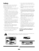
Setup Loose Parts Use the chart below to verify that all parts have been shipped. Step Qty. Description Use 1 No parts required – 2 Bagger mounting bracket Bagger side plate Spacer Bolt, (3/8 x 1-1/2 inches) Bolt, (3/8 x 1 inch) (for Z593 mowers only) Flange Nut, (3/8 inch) Curved washer 1 2 2 14 3 No parts required – Tighten all mounting bolts 4 Hood assembly Bags Clevis pin Hairpin cotter pin 1 3 2 2 Install the hood assembly and bags.
Note: Determine the left and right sides of the machine from the normal operating position. Step Step 1 2 Preparing the Mower Installing the Bagger Mounting Bracket No Parts Required Parts needed for this step: Procedure 1 2 2 14 2 14 14 Perform the following procedure to prepare the mower for attaching the blower and finishing kit. 1. Disengage the PTO, move the motion control levers to the neutral locked position and set the parking brake. 2.
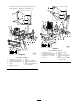
washers (3/8 inch), and 2 flange nuts (3/8 inch) (Figure 4, Figure 5, and Figure 6). Figure 5 For Z593 Diesel Mowers 1. 2. 3. 4. Figure 4 For Z500 Gas Mowers 1. Bolt, (3/8 x 1-1/2 inches) 2. Curved washer, (3/8 inch) 3. Bagger mounting bracket 6. 7. 8. 4. Spacer 9. 5. Bagger side plate Bolt, (3/8 x 1 inch) Curved washer, (3/8 inch) Bagger mounting bracket Bolt, (3/8 x 1-1/2 inches) 5. Spacer ROPS Flange nut, (3/8 inch) Side view of bagger side plate Holes to when installing the side bracket 8 6.
1. Tighten the bagger mounting bracket to the rear frame first. 2. Tighten the ROPS and side brackets to the side of the mower. 3. If the bagger mounting bracket moves side to side an 1/8 inch or more, install one or both of the spacers between the bagger mounting bracket and mounting plates (Figure 4, Figure 5, and Figure 6). 4. Tighten the bagger mounting bracket to the side brackets. Step 4 Installing the Hood Assembly and Bags Parts needed for this step: 1 3 2 2 Figure 6 For Z597 Diesel Mowers 1.
2. Install the 2 clevis pins into the hood assembly and bagger mounting bracket. Secure them with 2 hairpin cotter pins (Figure 8). Figure 10 1. Hood 2. Bag 3. 4. Bagger latch Latch hook 5. Position the bagger latch under the latch hook (Figure 11). Figure 8 1. Hood assembly 2. Bagger mounting bracket 3. 4. 6. Push down on bagger latch until it locks into place (Figure 11). Hairpin cotter pin Clevis pin 3. Install the bag tab into the notch in the hood assembly. Do this for all bags (Figure 9).
Step Step 5 6 Routing the Bagger Belt into the Blower Assembly Installing the Blower Assembly Parts needed for this step: Parts needed for this step: 1 1 1 Bagger belt (from Blower and Drive Kit) Procedure Blower assembly (from Blower and Drive Kit) Spring (from Blower and Drive Kit) Procedure 1. Install the belt around the blower pulley (Figure 12). 2. Install the spring to the idler arm and the peg on the blower assembly (Figure 12).
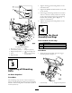
Figure 13 1. Bolt 2. Spacer 3. Locknut 5. 6. 7. 4. Spring 8. Spring installed Grass Deector L end of spring, place behind deck edge before installing bolt J hook end of spring 2. Slide the blower assembly peg into the pivot hole. For 60 inch mowers refer to Figure 14 and for 72 inch mowers refer toFigure 15. Figure 15 72 inch Mower Deck 1. Blower assembly 2. Mower deck, 72 inch (183 cm) shown 3. 4. Pivot hole Blower assembly peg 3.
Step Make sure the hooks are in the correct position. 7 Sizing the Upper Tube for 60 inch Mowers with Gas Engines Parts needed for this step: 1 Upper tube Procedure Figure 17 1. Spring loaded idler pulley 2. Short hook end 3. Note: This procedure is for 60 inch mowers with gas engines only. Long hook end 1. Measure up 3–1/2 inches (89 mm) from the bottom of the upper tube. Use the existing 3 holes as marks and then mark it in several places to create a line around the tube (Figure 19). 5.
Note: Remember to replace the grass deflector when the bagger is removed from the mower. Refer to Replacing the Grass Deflector. 1. Disengage the PTO and set the parking brake. 2. Stop the engine, remove the key, and wait for all moving parts to stop before leaving the operating position. 3. Lower the mower deck to the lowest height-of-cut position. 4. Remove the bags for viewing the tube under the hood. 5.
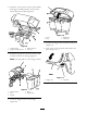
Figure 21 1. Hood plate 4. 2. Upper tube 5. 3. Hood in the down position 3/4 inch (19 mm) Edge of tube Figure 22 7. Once the 3/4 inch (19 mm) measurement has been achieved, mark the upper tube on the out side where the rubber seal protrudes out. This is marked to ensure the correct position for the upper tube when drilling the holes and connecting the upper and lower tubes (Figure 22). 1. 2. Upper tube 3. Rubber seal protruding out 4. Bagger hood Mark here against the rubber seal 8.
9. Slide the lower tube onto the boot and latch them together (Figure 24). Note: There is a latch on the top and bottom of the blower housing. Figure 25 1. Bagger hood 4. 2. Upper tube 5. 3. Drill 7/32 inch diameter holes here (use upper tube as a template) Lower tube Blower assembly 13. Remove the lower tube from the blower. Figure 24 1. Blower assembly 2. Lower tube 3. 14. Join the upper and lower tubes with 3 bolts (#10 x 3/4 inches), 3 flat washers (7/32 inch), and 3 locknuts (#10) (Figure 26).
Figure 27 1. 2. 3. 4. Figure 26 1. Lower tube 2. Upper tube 3. Flat washer, (7/32 inch) 4. 5. Locknut, (#10) Bolt, (#10 x 3/4 inches) Belt cover Blower assembly Pulley assembly Belt cover bracket 5. Latch 6. Belt cover notch 7. Belt cover support Step 10 15. Install the lower tube onto the blower housing and secure it with the latches. 16. Install the bags onto the bagger.
The bagger adds a lot of weight to the rear of the machine and may cause an unstable condition which could result in a loss of control. 1. Place caster weights on the front casters. 2. Install plate, nuts (1/2 inch) and lock washer (1/2 inch) under the frame and weight (Figure 28). Figure 29 3. Repeat for opposite side. 1. Top weight 2. Bolt, (1/2 x 2–1/2 inches) Note: All Z Master mowers receive the caster weights. 3. 4.
3. If adjustment is necessary, loosen the jam nut below the spring and tighten the nut directly below the yoke (Figure 30). Turn the nut until the correct measurement is obtained. Tighten the two nuts together and repeat on opposite side of unit. 4. Turn nuts clockwise to shorten spring length and turn counter-clockwise to lengthen the spring. 5. Engage parking brake, lever up. Figure 31 6. Measure the distance between the trunnion roller and the collar on brake rod.
Operation Without the grass deflector, bagger tubes or complete bagger assembly mounted in place, you and others are exposed to blade contact and thrown debris. Contact with the rotating mower blade(s) and thrown debris will cause injury or death. Note: Determine the left and right sides of the machine from the normal operating position. Important: Set the parking brake when leaving the machine unattended, even if just for a few minutes.
Figure 32 Figure 33 1. Emptying the Grass Bags Bag 2. Bottom handle 6. Repeat for the other bag. 7. Install the bag tab into the notch in the bagger support frame. Do this for both bags. 8. Lower the bagger hood over the bags. 9. Latch the bagger hood. Grass bags are heavy when full. Be careful when lifting or handling a grass bag that is full. 1. Disengage the PTO, set the parking brake, and chock or block the tires if on a slope. 2. Unlatch the bagger latch. 3. Open the bagger hood.
4. Unlatch the lower tube. 10. If you are changing to side discharge mode, ensure the grass deflector is installed and can be lowered into working position. 11. Remove the hood and bag assembly. 5. Remove the tubes from the bagger. 6. Using a stick or similar object, not your hands, to remove and clear the obstruction from the tube assembly. Using the Grass Deector Note: In most cases, the debris can be shaken out of the tubes. 7.
Bagging Long Grass sharply in confined places you may damage the attachment or other property. If the grass is ever allowed to grow longer than normal, or if it contains a high degree of moisture, raise the cutting height higher than usual and cut and bag the grass at this setting. Then cut and bag the grass again using the lower, normal setting. Trimming Always trim with the left side of the mower. Do not trim with the right side of the mower because you could damage the bagging tubes.
while loading and going over a curb. If a curb is higher than 6 inches (152 mm), cross it at a sharp angle with the deck fully raised. Use extreme caution when loading onto a trailer.
Maintenance Recommended Maintenance Schedule(s) Maintenance Service Interval Maintenance Procedure After the rst 8 operating hours • Inspect the bagger belt. • Inspect the bagger. Before each use or daily • Clean the hood screen. • Clean the bagger. Every 25 hours • Inspect the bagger belt. Every 50 hours • Grease the idler arm. Every 100 hours • Inspect the bagger. Cleaning the Hood Screen Check belts for cracks, frayed edges, burn marks or any other damage. Replace damaged belts.
Figure 36 1. Latch 2. Bolt Figure 34 4. 5. 6. 1. Idler pulley 2. Mower deck pulley 3. Spring Peg Belt Blower pulley 3. Blower assembly Greasing the Idler Arm 6. Install the spring as shown in Figure 35. Grease the bagger belt idler arm (Figure 37) every 50 hours. Figure 35 1. Spring loaded idler pulley 2. Short hook end 3. Long hook end Figure 37 7. Pull back on the spring loaded idler pulley and install the belt onto the spring loaded idler pulley (Figure 34).
3. Check the upper tube, lower tube, bagger hood, and the blower assembly. Replace these parts if they are cracked or broken. 2. Remove the damaged or worn grass deflector. 3. Place the spacer and spring onto the grass deflector. Place the L end of the spring behind the deck edge. 4. Check the bags, bagger frame, and screen. Replace any parts that are cracked or broken. Note: Make sure the L end of the spring is installed behind the deck edge before installing the bolt as shown in Figure 38 5.
Storage 1. Clean the bagger attachment. Refer to Cleaning the Bagger. 2. Inspect the bagger attachment for damage. Refer to Inspecting the Bagger. 3. Make sure the bags are empty and thoroughly dry. 4. Check the belt for wear or cracks. 5. Store the machine in a clean, dry place, out of direct sunlight. If you must store the machine outside, cover it with a weatherproof cover. This protects the plastic parts and extends the life of the machine.
Troubleshooting Problem Possible Cause Corrective Action Abnormal vibration. 1. Cutting blade(s) is/are bent or unbalanced. 2. Blade mounting bolt is loose. 3. Loose blower pulley or pulley assembly. 4. Worn bagger belt. 5. Blower fan blade(s) is/are bent or unbalanced. 1. Install new cutting blade(s). 2. Tighten the blade mounting bolt. 3. Tighten the appropriate pulley. 4. Replace belt. 5. Contact an Authorized Service Dealer. Reduced bagging performance. 1. Low engine speed. 2. 3. 4. 5.
Problem Blower impeller does not spin freely. Possible Cause 1. Plugged blower. 2. Impeller not aligned. 30 Corrective Action 1. Remove debris, leaves or grass clippings from the blower impeller. 2. Contact an Authorized Service Dealer.
The Toro Total Coverage Guarantee LCE A Limited Warranty Conditions and Products Covered Owner Responsibilities The Toro® Company and its afliate, Toro Warranty Company, pursuant to an agreement between them, jointly promise to repair the listed Toro Products if defective in materials or workmanship. The following time periods apply from the date of purchase: You must maintain your Toro Product by following the maintenance procedures described in the operator’s manual.