
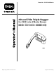
Operator's Manual


Note: Deter mine the left and right sides of the mac hine from the nor mal operating position.
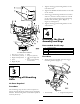
Step
1
Preparing the Mower
No Parts Required
Procedure
P erfor m the follo wing procedure to pre pare the
mo w er for attac hing the blo w er and finishing kit.
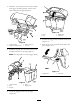
1. Diseng ag e the PTO , mo v e the motion control
lev ers to the neutral loc k ed position and set
the parking brak e .
2. Stop the engine , remo v e the k ey , and w ait for
all mo ving par ts to stop before lea ving the
operating position.
3. R e pair all bent or damag ed areas of mo w er
dec k and re place any missing par ts .
4. Clean the mo w er of any debris on the dec k or
rear par t of the mo w er to ease installation.
Step
2
Installing the Bagger
Mounting Bracket
Parts needed for this step:
1
Bagger mounting bracket
2
Bagger side plate
2 Spacer
14
Bolt, (3/8 x 1-1/2 inches)
2
Bolt, (3/8 x 1 inch) (for Z593 mowers only)
14
Flange Nut, (3/8 inch)
14
Curved washer
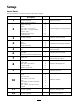
Procedure
Important: Do not tighten an y bolts until
both side brack ets and ba g ger mounting
brack et ar e fit loose on the machine.
R efer to Tightening the Mounting Bolts f or
the cor r ect pr ocedur e to tighten the bolts.
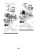
1. R emo v e the bolts , n uts , and w ashers holding
the roll bar to one side of the mac hine . Discard
the n uts , bolts , and w ashers ( Figure 4 , Figure 5 ,
and Figure 6 ).
2. Install the bag g er side plate and the roll bar
section to the side of the mac hine using 4 bolts
(3/8 x 1-1/2 inc hes), 4 cur v ed w ashers (3/8
inc h), and 4 flang e n uts (3/8 inc h) ( Figure 4 ,
Figure 5 , and Figure 6 ).
3. R e peat the ste ps abo v e for the opposite side
( Figure 4 , Figure 5 , and Figure 6 ).
Note: Mak e sure the cur v ed w ashers are
installed as sho wn in Figure 4 , Figure 5 , and
Figure 6 .
4. Install the bag g er mounting brac k et to the left
and right side bag g er brac k ets with 4 bolts
(3/8 x 1-1/2 inc hes), 4 cur v ed w ashers (3/8
inc h), and 4 flang e n uts (3/8 inc h) ( Figure 4 ,
Figure 5 , and Figure 6 ).
5. Install the bag g er mounting brac k et to the
rear frame of the mac hine with 2 bolts (3/8 x
1-1/2 inc hes) (use 2 bolts (3/8 x 1 inc h) for
Z593 mo w ers as sho wn in Figure 5 ), 2 cur v ed
7