
Operator's Manual


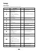

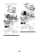
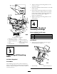
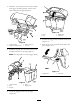

Figure 6
For Z597 Diesel Mowers
1. Bolt, (3/8 x 1-1/2 inches)
6. ROPS
2. Curved washer, (3/8 inch) 7. Flange nut, (3/8 inch)
3. Bagger mounting bracket 8. Side view of bagger side
plate
4. Spacer
9. Holes to when installing
the side bracket
5. Bagger side plate
Step
3
Tightening all Mounting
Bolts
No Parts Required
Procedure
T he follo wing ste ps are the cor rect sequence to
tighten the side brac k ets and the bag g er mounting
brac k et. All mounting bolts need to be tor qued to
35 ft-lb (48 N ⋅ m).
1. Tighten the bag g er mounting brac k et to the
rear frame first.
2. Tighten the R OPS and side brac k ets to the side
of the mo w er .
3. If the bag g er mounting brac k et mo v es side to
side an 1/8 inc h or more , install one or both
of the spacers betw een the bag g er mounting
brac k et and mounting plates ( Figure 4 ,
Figure 5 , and Figure 6 ).
4. Tighten the bag g er mounting brac k et to the
side brac k ets .
Step
4
Installing the Hood
Assembly and Bags
Parts needed for this step:
1
Hood assembly
3
Bags
2
Clevis pin
2
Hairpin cotter pin
Procedure
1. Install the hood assembly onto the bag g er
mounting brac k et ( Figure 7 ).
Figure 7
1. Hood assembly 2. Bagger mounting bracket
9